Showing posts with label A10. Show all posts

Monday, 28 July 2025

FH - still on the bench, but looking good!

 It's been a while, or it feels like it. It's actually almost a week since I did anything to the FH - I've done a couple of railway turns and the weather has been a bit wet.

The head bolts are torqued to 32 lbs ft or so. I tightened them down using a 1/2" square ratchet (as per the manual, as tight as I could get them), then checked them with a torque wrench set to 32 lbs.ft. - so they may be tighter than that. The 32 lbs.ft seems to be bandied around a lot in connection with iron-head A10s.

This is the drive side cylinder - 140 psi or so. this was showing 75 psi on the last test, and is the cylinder that weeps oil.

This is the timing side cylinder, which showed 95 psi in the last test.


Now, obviously these numbers are a lot higher than we saw before, but don't be fooled, this is partly because I had the throttle open during the test - it was closed previously. The big win here is not the high numbers, but the fact that the two cylinders are no longer 20 psi, or around 25% different.

I bought a couple of sets of rocker box gaskets on eBay - they are identical to BSA A10 rocker box gaskets, though the tappet cover gaskets are different. I fitted these with Wellseal last time, and destroyed them lifting the rocker box. This time, I'm going to use Threebond 1215 on one side with grease on the other.

I'll have to find a moment to put it on.

Monday, 6 May 2024

FH - oil pump

Over three years ago now I pulled this sludgy oil pump out of the timing case, planning to look at it and consider it for further use. It would barely turn.


Since then, much has come and gone (some of it twice) but I have stripped the pump and freed the high spots in the drive that caused the seizure. With these Mazak/Zamak castings, impurities in the alloy corrode and cause the casting to swell and crack, in this case causing high spots in the drive gear bore and damage to the circlip recess - though fortunately nothing irreparable. 


The body casting had a bit of carbon in the smaller bores:

The ultrasonic bath fixed that, and revealed some scoring. If this leads to excessive wet-sumping we will have to replace the pump.


With it all back together and working, I realised there was a thrust washer missing, which is supposed to fit under the circlip. I'll have to make one.

Tuesday, 21 November 2023

Ariel Huntmaster vs. BSA A10

The purpose of this post is to look at the engine specifications, or the state of tune, for the various Huntmaster models and see how they compare with the closest BSA A10 models. We'll figure out which A10 is equivalent to the Huntmaster.


Here are the areas under consideration and the data I've found from reviewing the books:

Compression

  • 6.5:1 Golden Flash & Huntmasters 1954-1959 
  • 7.25:1 Optional for Huntmasters 1954-1959, standard for Cyclones
  • 8:1 Road Rocket, Optional for Cyclones
  • 8.3:1 Super Rocket
  • 9:1 Rocket Gold Star

Camshaft

  • 334 "standard" - fitted to the Golden Flash from 1950 - 1959 & Huntmasters 1954-1959 
  • 356 "sports" - Road Rocket, Super Rocket until 1959, Golden Flash from 1960 & Cyclone
  • 357 "race" - Super Flash, Spitfire Scrambler and Rocket Gold Star. Also fitted to the Super Rocket from 1960.
  • 358 "acceleration".

Valves

  • Inlet 1.406 Huntmaster 1954 -1959, Golden Flash 1950-1957, Super Flash / Rocket 1953-1960
  • Exhaust 1.375 Huntmaster 1954 -1959 Golden Flash 1950-1957
  • Exhaust 1.381 Super Flash / Rocket 1953-1960
No head changes for Cyclone

Carburettors

  • 76/276 (1 1/16" bore) - Rigid and plunger framed Golden Flash, also swinging arm Golden Flash & Huntmasters in 1954.
  • 10TT9 (1 1/16" bore) - Super Flash and Road Rocket, also Super Rocket until 1961.
  • 376 Monobloc (1 1/16" bore) - Golden Flash swinging arm frame, Huntmasters 1955 to 1959 and Spitfire Scrambler (1956 - 1959).
  • 389 Monobloc (1 1/8" bore) - Golden Flash 1960 on.
  • 389 Monobloc (1 5/32" bore) - Spitfire Scrambler (1960 on), Super Rocket (1962 on) and Rocket Gold Star.
No carburetter changes for Cyclone

Conclusion

So there you have it:
  • A standard Huntmaster is equivalent to a BSA Golden Flash, the most basic A10
  • A Cyclone is close to a BSA Road Rocket, though with a slightly lower compression ration unless it is fitted with the optional 8:1 pistons
  • My bike will be equivalent to a standard specification Ariel Cyclone.

Saturday, 7 August 2021

FH Front Mudguard

I have had a bit of a debate with myself about which mudguard to use on the FH. It arrived with this one, which is an A10 front mudguard and is not so odd as you might think - it fits, is larger and therefore more protective and it is much stronger than the proper Ariel mudguard which has a reputation for cracking.


It's ugly as sin, but it does suggest that the previous owner moved in Ariel circles as this is quite a common mod. Another option was to buy an earlier mudguard, the ribbed C section guard used with the single sided brake, which is much better looking and matches the rear mudguard.

The final option is to use this, the correct one (i.e. the one which is prone to cracking!), which came from eBay and is in pretty good shape. It does have the beginning of two cracks which will need reinforcing...


The A10 mudguard had this stay in it, which is actually an Ariel centre stay that has been extended in width to suit the BSA guard. The PO was clearly handy with the welder.


I've chopped a little out of the centre to bring it back to size and re-welded it.


It all fits, so that's another job off the list:


Thursday, 27 June 2019

Dry Build - Siting the Oil Filter

These plain journal engines run close tolerances and need a decent oil filter. Modern oils keep the dirt in suspension and if there is no filter, the oil becomes contaminated very quickly.

The SQ4 has a Norton commando oil filter, like this one, fitted under the gearbox where:
  1. you can't see it
  2. you can get to it easily
  3. it doesn't ground on kerbs
We'll need a similar site for the filter on the FH.

There's a lot of space behind the engine, between the engine/gearbox plates - but not for this filter, which is marginally too big for this location.


Beneath the swinging arm and in front of the mudguard is a likely location used by many FH owners. I'll need to find a location where I can easily mount the filter and where the oil lines will be able to get to and from it without kinks - and it must also fulfil the other criteria I listed above.


This is probably no good - there is nowhere to mount to and the oil line routing could be a bit tortuous:


This is an example of a mounting used in that area:


This one is on AOMCC forum member Steve Carter's Ariel Cyclone.

And another - this is AOMCC Kieth Mettam's filter:


Another one from Steve Carter, this well used Huntmaster carries a Morgo filter - these are smaller than the Commando filters and easy to place - but they are quite expensive and it makes sense to me to use a unit I already have elements for, commonality of spares and all that:


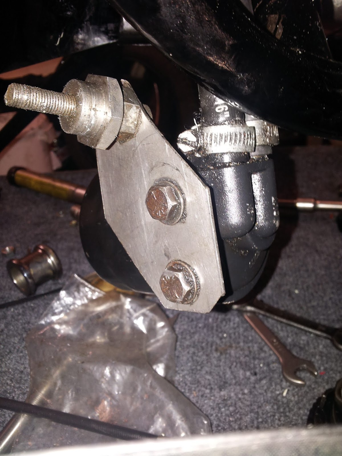
This is my choice. I'm using a mock-up bracket, made from a bit of 20 swg sheet, welded to an old footrest bar sleeve nut and placed in the sidecar lug beneath the swinging arm:


It's too far back, and the oil lines foul the gearbox casing:


Time to cut it up and shift it around:


To become this ugly but effective thing, including a bit of butt welding practice:


Also pictured is the beginning of a special bolt that will locate the filter bracket in the sidecar mount.


This is better. It's further inboard to allow the oil lines to pass the gearbox outer casing, and further forward to guarantee the filter clears the mudguard and rear wheel:


The next step is to replace the bracket with one made from 3-4 mm sheet, and finish the special bolt that holds it in place. I'll use the same old sleeve nut, but I will probably machine a journal in it to fit in the hole properly.

Here's the finished bolt:


It's in the wrong side, but I'm just testing for fit. I wanted to make it look like the swinging arm nuts.

I'm tubing up using a mixture of Huntmaster and BSA A10 oil lines. The long A10 lines stretch from the engine right around under the gearbox to the oil filter:


I've spent a long time faffing around with these connections, even considering moving the filter altogether. In the end, after a session mulling it over one night in the workshop with my son, we concluded we could get it all in there if we modified the fittings:


I've shortened the unions in the lathe and gained about 5/16" which is enough to give the gearbox it's full range of adjustment. This allows the gearbox to move and the oil lines to follow the routes I'd laid out. A minor problem is that the return to the tank is touch on the long side and the route has to cover a 120° bend on top of the gearbox, which is a bit unsightly.


Final filter bracket:


Thursday, 14 March 2019

FH Crankshaft 2 Cleanup 2 - Sludge Traps & Galleries

Having got the crankshaft to a stage where I believe it is mechanically acceptable, we now turn to a vital area which is easy to overlook if you are not listening to advice or reading the books.

The ubiquitous crankshaft sludge traps - large drillings in the crankshaft which are designed to centrifugally extract solids from the circulating oil, and keep it out of harms way. These days, we use high-detergent oils and filters - the oil carries solids in suspension and the filter collects it, and there's the rub - when filling your barn find with new oil you really don't want the modern oil releasing the built up deposits of the last 50 years into your lubrication system, so you must clean the traps and banish the sludge forever before you run the engine. Never more true than if that engine belongs to an Ariel Square Four, which has very small (3/16" diameter) sludge traps.

No one wants a seized big-end, as the appearance of a connecting rod through your crankcase can be upsetting to younger viewers.

In an FH, A10 or A7 crankshaft, and many others, the sludge trap is in a large drilling through both big ends which is closed with a threaded plug at each end. The big end oil feed comes into this gallery from the timing side main bearing, and both the big ends are fed by 3/32" ports drilled directly into the gallery.


The gallery is provided with a thin tube, which acts as an oil way; until it is very blocked, the solid deposits form outside of this tube, flung away from the centre of the crankshafts rotation as you would expect. The tube features two or four holes to distribute oil to the big ends, and another hole by which it is located by one of the flywheel bolts, and one end is belled out to locate it in the large diameter of the gallery.


The tube is located at the drive side end on one of the gallery's closing plugs. The plugs are soft mild steel, very tight, often staked in and they are optimistically equipped with screw driver slots. People tell you not to bother with your impact driver - I tried it once, destroyed the slot and reached for the welder. The welder, however, is not the only way.

I started this morning with the 100 mm grinder, with a twisted wire cup brush in it, to clean up the rust (I also had it on the rear mudguard, but that is another story for another day).


My usual approach to these is to weld a bit of 1/8" sheet into the slot. This bit of 14 swg bar was a bit small, and it wasn't clean enough:


Grab it with an adjustable and turn...


And Robert is revealed as one of your mother's siblings.


That is the timing side. The drive side, at the end of the oil way, will be worse. I loosened this plug using the 'welded bar' method, but broke the bar trying to get it out. The moral of the tale there is to take more care - make a suitable bar and weld it in to a prepared slot. Or, as I did here, drill two 1/8" holes, about 3/8" deep; grind flat the ends of two thick masonry nails (hard, and very useful), and use them as a makeshift pin spanner:


Here's another approach: Vincent van Ginneke sent me this picture; he's using a large vice to hold a 1/2" drive screwdriver bit in the sludge trap plug slot. Normally, if you try a screwdriver the bit will  slip out of the slot in the plug; Vincent clamped the crank, screwdriver bit and T bar in a large vice, with just enough pressure to prevent it from dropping out and by turning the T bar a tiny bit (about 1/8th of a turn) and opening the vice also a tiny tiny bit he was able to hold enough pressure on the screw driver bit that it would stay put in the slot.


As I mentioned earlier, the drive side is worse - it's totally full:


The plug on the right is the drive side one. The nose locates the end of the sludge trap tube:


Because the tube is surrounded by solid deposits, it can be hard to shift. A hammer and a drift can be useful here - you can see the tube emerging on the left:


And that is it. That's most of the contents of the tube - the rest of it is still inside the crankshaft.


You'll want to scour that out, like this:


You also want to make sure the oil ways are clear. This is a 3/16" twist drill going through the timing side main bearing oil way, clearing the path to the sludge trap gallery. You can just see it emerging in the gallery:


You can clear the big end oil ways with a 3/32" drill.


When new, these oil ways have a 'teardrop' scooped out of the surface to distribute the oil across more of the big end width. Since these are -0.030", these 'teardrops' have long since been ground out. We can put them back with the Dremel:


When we've done, we'll polish the surface with Emery and wet'n'dry.

These are the flywheel bolts. One of them (guess which one) holds the sludge trap tube in place - that is a 3/8" BSCY intermediate tap, waiting to clean up the threads.


Both the bolts and the female threads in the crankshafts are easily cleaned up; I may replace these bolts when I assemble the engine.

The final step is to clean the remaining rusty debris from the flywheel and the crank webs, with various wire brushes. This done, I've sprayed the parts with ACF50 for storage - we'll put it all together when we come to assemble the engine.


Thanks for reading, and I hope you found it useful.