Showing posts with label side stand. Show all posts

Monday, 23 October 2023

FH - a bit more assembly

 A few more bits fitted today - the prop stand is on:


…and having received the correct dome head bolts for the front mudguard, the wheel is back in. Obviously this still needs a lot of work, but once the back wheel is on (more work required on the FERC) it will let me move the chassis about and tidy up the workshop.


Wednesday, 15 March 2023

W/NG - Field Stand Springs

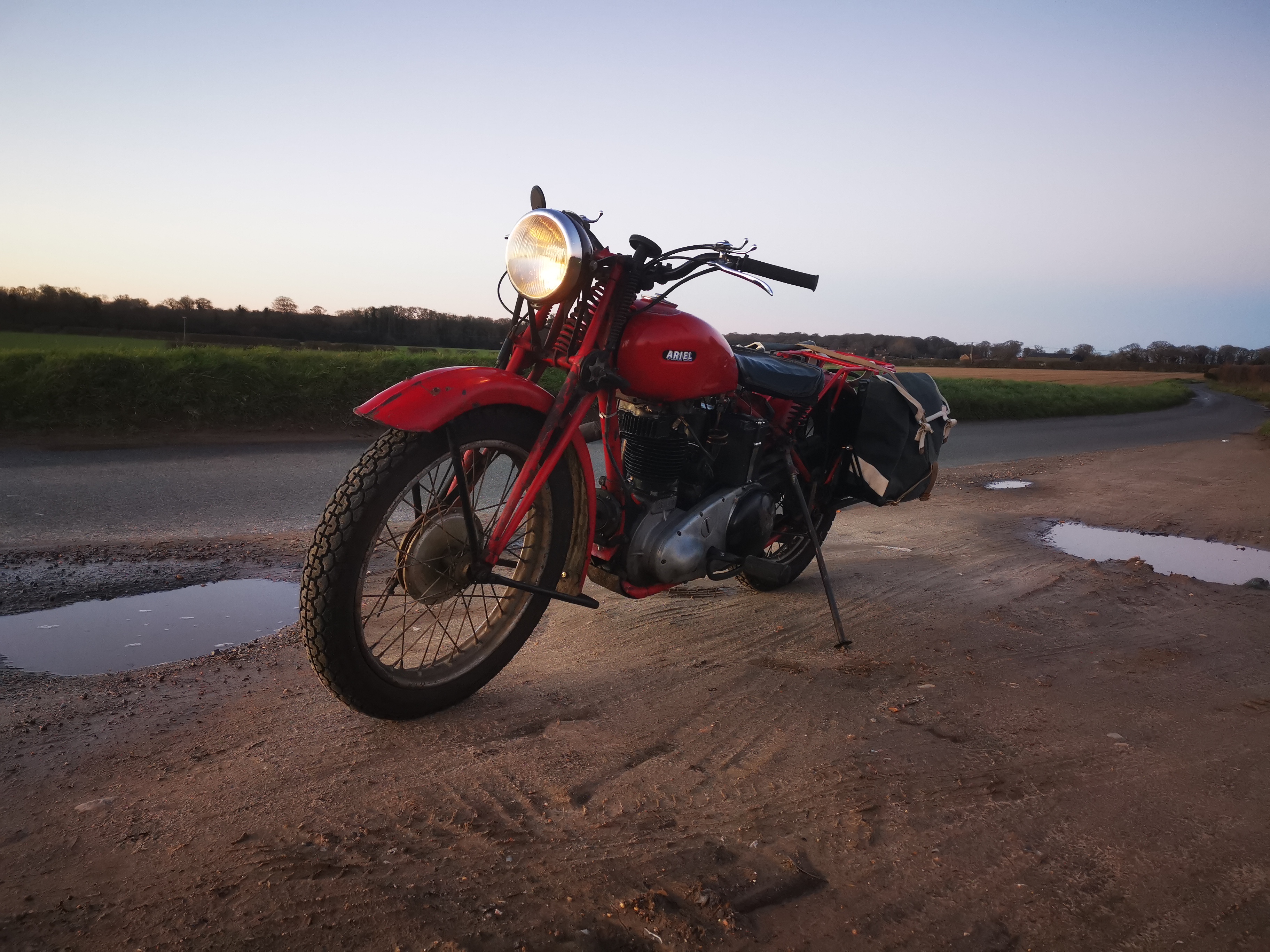
 Whilst the field stand on the W/NG is a fine thing, I don't use it very much as it's a bit of a nuisance to get it down and back up again. The stand is not quite as shown in the factory parts books and is probably not original.

The same could be said of the spring clip, which looks a bit like the earlier type but is too short - it’s not only stiff but now that I have the panniers fitted, it allows the stand to foul the pannier frame bracket.

So, inspired by fellow W/NG owner and YouTuber Alan Moore, who compiled an excellent instructional video on this subject, I resolved to make a pair. You can buy these clips now from various sources (including the AOMCC Singles Spares) but I decided carry on with the plan to make my own to prove that I could.

I started with a simple bit of wire to develop the profile of the spring:


That gave me the length and the shape I would need and I used this to make a card template. Following Alan’s example, I bought a couple of lengths of CS95 spring steel from eBay, and used the Rothenburger MAPP torch to normalise them, by heating to cherry red and cooling in air.

This process left the hard spring steel soft enough to drill and to cut to shape with the snips.


With the blank cut and drilled I could bend them to shape. The first one took a bit of faffing around with bits of round bar in the vice, pliers and swearing; for the second one I welded up this little tool which made the bending much easier. I left the sharp bend near the mounting holes until last.


Using the tool, it was easy to make those reverse bends. It’s the fact that they are so close to each other that makes bending the spring difficult without a pair of bars fixed close together.


Once I had both springs bent up, I could fit them to the bracket on the bike and ensure that:
  • The stand would be gripped adequately
  • The ends of the spring would be open enough to allow the stand to be pushed in
I messaged Alan through YouTube to ask if he had had any problems with the bends opening during heat treatment - he hadn’t (and nor did I).


I built a little barrel furnace out of a 5 litre beer keg, some ceramic insulation, a fire brick and some fire cement. The first step was to heat the springs cherry red; you can see the torch is low on gas in this picture as the shroud is glowing. I swapped gas cylinders after this and used the almost-empty cylinder for tempering.


Next, quench in oil:


After cleaning the oil off, you can test the hardness with a file. The file just skates off the hardened steel and will not mark it. Next, you clean the oxide off with Scotchbrite so that you can see the colours form during tempering:


Next job is to temper the whole spring to 350°C, which is the blue colour you see here and quench in water to stop the process. One of these springs is polished post heat treatment, the other is straight out of the water bath. They certainly sound springy after tempering!


Here's a rather hasty picture of it in place - in fact this is the first fit though it took a while to get it there. The old springs were fitted with some oddball screws and wing nuts, possibly 3/16" BSW - I think I must have done my previous, pre-heat treatment trial fit using these screws, because the springs don't fit with the 1/4" CEI bolts I have in there now as the holes are tight on the bolts and are not quite in the right place. Silly boy. 

So, having spent ten minutes with a grinding wheel in the Dremel moving those holes a little inboard and opening them to about 7 mm had the springs fitting easily - or more easily. If I have to make another pair of springs, I would allow a bit more space for the nuts & bolts - the one closest to the camera is a bit tricky to get to.


And it works! The spring is much, much easier to use than the old one which means the field stand will get used more often - currently you have to align the stand with the spring and kick it to get it in, which is tricky if you are on the bike. Right now, with only a couple of tests the spring temper looks to be acceptable - though I wonder if I have overheated it - it's springy but not overly strong. Lastly, you can see from the picture that the field stand is now clear of the pannier frame.

So that's it - all done for the moment. I will put a safety chain or perhaps a zip tie around the field stand and the pannier frame, to keep the frame clear of the road should the spring break or the stand bounce out of it. We'll see how it goes.

Monday, 28 March 2022

Charlie's Shed - Making a sidestand

 The sidestand fitted to Anstey-framed Ariels is a poor affair that does not extend very far from the frame and has a very small foot which combines to make the use of the stand a very precarious and risky operation. I never use it. 

However, the bike is a heavy old thing which would benefit from a decent sidestand so in this episode I'll show you how to make one.

I bought a leg, a while back, from eBay. It's from a Suzuki TS125 trail bike, so it is very long and it came with a spring and a M10 x 1.25 bolt. Doing this again, I'd probably buy a Triumph or Enfield leg as I ended up cutting a lot of length off this one.

The sidestand is going to bolt on, but I'm not a fan of clamp on types so this is going to bolt across the two bottom frame rails forward of the sump plate. A piece of steel bar, 6 mm x 35 mm spans the frame. I start by putting a 45° bend in a short length at one end, to start to get an idea of how it will look on the bike and what sort of leg length I will need, where it will sit in the 'up' position and where the stops will need to be. I drill a 10.5 mm hole for the bolt and fit the leg:


The first decision I make is that the spring will be underneath, not above the leg as Suzuki had it. I'll cut the peg off and smooth the area:


While the 6 x 35 mm flat bar can provide the 'down' stop, it needs extending to provide the 'up' stop. I make a piece with a double prep and weld it on:


Some shaping with hacksaw, files and the linisher gives us two stops:

The stand is going to be held on the frame rails with three 1/4" U bolts, one on the drive side and two on the timing side. Here's a trial fit of the first one:

With the assembly in place we can look at the leg length, and the angle it is going to make with the ground. Obviously if the stand's touch down point is further away from the bike's centreline, the bike is more stable. We don't want the stand leg too short, but leaving it like this won't allow the bike to lean enough.

Next, we need to stiffen that bar. It's stiff, but this is a heavy machine and we don't want a rider sitting on the bike while it is on the stand opening our stand bracket out. The stiffener is a piece of 20 x 3 mm flat bar


The stiffener also provides somewhere to mount the spring lugs. I made these from a bit of 10 mm round bar on the mini-lathe:


One of the key issues is to get the lugs in the right place such that the spring holds the leg firmly in both positions, without the spring fouling anything as it moves:

There was way too much slop between the stand leg and the mounting bar. I built up the bearing surface with weld and cut it back on the linisher to get it to about 7 mm

It's much less wobbly. Obviously wobble here will affect the lean of the bike when it's on the stand.

Time for another fitting. At the previous trial fit, I marked the position of the timing side U bolts, so now I can drill the holes. I haven't yet trimmed the mounting bracket, but I have trimmed the leg. Here are all the bits:


The bike has a lean of maybe 5°, which is fine.


Time to start finishing the leg. Here's the foot, cut from a bit of 3 mm sheet. The sheet happened to have a hole in it, I'll fill it up later:


Gosh that was quick. In this next picture, the foot is partially welded on and I have made the foot finder from some 10 mm round bar and another bit of 3 mm sheet. To start with, I fitted the stand to the bike in the up position and held a 200 mm length of the round bar in place, deciding where I wanted the foot finder - it needs to come out behind the foot rest and to do that I needed a bend. Once I had the bend formed I held the round bar on the foot with a spring clamp to see if it was in the right place, and I was able to see how long the bar needed to be and where on the foot it needed to be fixed. I tacked it on the foot.

Next I made a 25 mm square pedal, and curved it a little to emulate the shape of the brake pedal. I tacked that on the end of the bar and refitted the stand, which revealed various issues. These were resolved by removing the leg and holding it on the vice, heating the round bar to perform the bends I wanted - the bar curved around the exhaust, but not tightly enough, and the pedal was not square to the bike in two axes. A bit of heat soon fixed those issues. 

That's it for now. The stand is back in position and working:


I'll run around with it for a while and see how it goes. I still need to ease the 'u' bolt holes on the timing side and trim the end of the bracket before painting, but for now we need to shake it down.

Friday, 7 January 2022

FH Dry Build - that sidestand again

With the exhaust in place, I can look again at the sidestand and see where the 'foot finder' pedal needs to be, before I weld it on. I start with the sidestand fitted and the pedal held in place with a tool makers clamp, so I had some idea of where to weld it such that it wouldn't hit the exhaust.

I had the TIG set to 45 A to weld it all around. It's quite a big weld for my set up, but as long as I didn't drag the arc out it was fine - of course, with a fillet, drawing the arc out is what I always do to keep the tungsten out of the weld pool!

I tweaked the pedal a bit once the weld was done to get it in the right place...

I haven't used the stand yet, but it looks like the pedal will clear the ground:


Monday, 6 December 2021

FH Dry Build - fixing the side stand

The kit of parts came with a side stand that fitted the frame lug but otherwise is unlike any side stand I have seen on an Ariel - from a bit of Googling, it appears to be Triumph one. I chose to modify it to fit the FH - in fact I would use it to make a replica of an Ariel one.


You can always get help with your Ariel - from fellow members of the AOMCC, or perhaps members of other Ariel clubs around the world. There are a few. This next picture came from such a source and shows the business end of an Ariel side stand:


The donor stand had a small hole for the spring. Since the first bit to get right was the fitting of the stand to the frame and the ability for it to hold itself safely in both positions (Ariel side stands stay down until you flick them back with your foot), I needed to make a peg for the spring. Another job for the mini-lathe:


Unfortunately, the first attempt revealed that I didn't have enough stretch in the spring - the stand would go down and come up but the spring would fall off before the stand was in the parking position.


I had to cut the peg off and re-weld it 3/4" further down the leg. I need a few more bits:

Side stand kit

Here's some more AOMCC help. Those feet belong to Lee Mallabone, and that's his side stand - he's showing me what shape the foot needs to be:


Using my hacksaw and the linisher, I trimmed the foot I'd made to match the original that Lee showed me. It's close enough - it's actually a bit bigger, which can only help out in the field:


Here it is back on the bike. I've relieved the inside of the clevis a little such that it comes around the lug a bit more, but to be honest I am not sure I want it to stay down - which it doesn't:


However, at the other end of the travel, it doesn't come up as far as I think it should:


Have a look at this:


Either I need to modify the clevis so that it will move further in both positions (which will have the effect of making it stay down) or I have to change the frame lug to relieve the stop at the parked end.

The next job is to trial fit the exhaust - then I can work out where the 'foot finder' pedal needs to go. More on that later.

Friday, 6 December 2019

What's that ominous noise?

Last weekend, my Sunday morning jaunt ended after 1.5 miles with a screech/rattle (strange sound in between the two) that has appeared while accelerating up a hill. I think it's transmission - out of gear the engine appears to be fine. Turning the rear wheel by hand with the clutch out and the bike in gear sounds rattly - I think I will have to take a look at the clutch. The noise changes with clutch operation, less harsh perhaps and appears to be related more to road speed than engine speed.

Of course, as I write this I sound like I have a misplaced confidence that no Square Four owner has any right to - you are always worrying that it is going to lift it's skirts above it's knees and show you a connecting rod when you were least expecting it. This time, I arrived home with the engine ticking over sweetly and it continued to do so when I parked up. 

Running it on the stand, I couldn't replicate the sound, but I did notice the rear wheel is a lot more wobbly than it was when I built it.

A week or so later, after some busy time at work and contemplating that I might get the CX500 on the road, I found a bit of time to pull it apart. It's worth remembering that older bikes are often easier to fix than newer ones - my Square is a lot less complex than the Honda and it's much easier to work on.

All I need is this handy kit that I found in the bike's toolbox:


Or - not. Falling at the first fence, I found that I did not have a 3/8" AF box spanner in the tool roll. This odd ball size fits not only the clutch centre screws but crucially the exhaust pipe clamps - so I couldn't even start the job. I made a note to buy one for the tool roll.

With the pipe off, I slackened off the brake pedal and disconnected the brake light - that lets you remove the clutch dome. I might see if I can get a better shine on that patina:


With the right tools, the clutch plate came off perfectly:


And it revealed a loose clutch centre nut, just as had been predicted by the AOMCC forum panel of experts. The nut was loose but still in place, but it probably wouldn't have come loose at all if I had been a bit more thorough with the tab washer:


Watch:


The clutch plates are getting thin, but I have no wish to re-cork them right now, nor any cork; they need pulling out with this bit of hooked wire I keep in the tool box:


Slightly sticky. That's grease from the centre bearing:


Here it is again - we will have to be sparing with it on reassembly. The splines are no worse than when they went in back in 2014:


And again. Those screws are in place but very loose:


As can be seen in this video:


Thankfully, all looks well under the primary chain cover:


The shock absorber nut is exactly as it was when I fitted it back in 2014:


Sprocket looks fine:


Having removed the chainwheel and carefully removed its bearing (with the twelve needle rollers) I set about removing the rear half of the chaincase. When it wouldn't come free, I remembered that the rear upper chainguard is bolted to the chaincase and that the bolt lives under the battery. This has not been off for ages as it has been no trouble at all:


Here's the bolt I'm talking about. You have to remove the coil as well:


Once behind there all looked fine & dandy:


Oil filter head looks OK:


At close of play, the rear chaincase was back in place, sealed with Threebond 1215:


The next day I tensioned the primary and put the chainguard and the coil back in place, and the following day I put the primary case back together:


Next came the clutch rebuild. This time I paid much closer attention to assembling clutch basket to the sprocket, and the centre to the mainshaft retaining both with Loctite 243.


The mini-lathe is a useful beast. Here I'm turning up a new spacer to fit between the primary chaincase inner half and the frame in stainless steel. It's 1/2" long, 11/32" ID for clearance on a 5/16" bolt and 3/4" OD:


This is the truly awful side stand. I never use this, as it is far too short and consequently precarious. The tie wrap is there to make sure the spring cannot become disengaged from the lug on the leg, which would leave the leg flopping about:


Assembling the battery carrier and it's spacers:


And all back together.