Showing posts with label repair. Show all posts

Thursday, 15 August 2024

SQ4 - fuel tank

 Some years ago the Square Four got a new fuel tank in original paint from Yeoman’s Motorcycles. It was pretty shabby but it still had the coach lines picked out in gold paint to show where the Ariel craftsmen put them all those years ago.


As you can see the paint is very faded. The Square Four wore this tank for several years but eventually I decided that it was really too far gone. I didn’t really want to repaint the whole tank and lose all the patina, so inspired by Graham Ham’s book about his Speed Twin ‘Daisy’ I resolved to clean up the paint as best I could and enhance the gold lines a little bit.


The areas that were worse affected were around two weld repairs where the tank badge carriers had been refitted. The paint here was burnt and discoloured and no amount of rubbing down was going to bring that back. I used a matching spray paint (from stock I had accumulated years ago) to blend these areas in to the rest of the paint. Rubbing all the paint back with various grades of wet and dry from 240 to 2000 brought the tank back to life enough. 


I then used some old jet black gold lacquer and some 3 mm PVC masking tape to put the lines back in. When these were mostly dry I rubbed over them with a dirty glove to dull them down. This works reasonably well when I timed it correctly but if the paint was too dry it didn't pick up the dirt from my gloves.


It needs more work of course, but it's getting there for sure.


Sunday, 19 January 2020

Badge Repair

Motorcycle badges are often held in place with clips over posts, plastic, die cast zinc or otherwise and they are often quite weak. Removing the clips with a Dremel often helps but sometimes you find the badges already broken.

This badge from the front of the CX500 is a typical example. This time, I chose to glue two M3 screws to the back of the badge and retain them in place with nuts and Loctite 243. The badge is fixed to the screws with Araldite 5 minute Metal adhesive.


I prepared the badge by drilling out the broken posts with a 6 mm twist drill.


The screws were held during setting with this simple wooden jig, drilled with 3 mm holes at the proper pitch for the badge. This guaranteed the screws would be parallel to each other and perpendicular to the badge:


I modified the screw heads using the lathe to match the 118 degree included angle of the 6 mm drill, to maximise the contact with the badge:


The CX is back together now and starting to look a bit more presentable:


Saturday, 2 February 2019

Dry Build - Repairing the Chain Guard

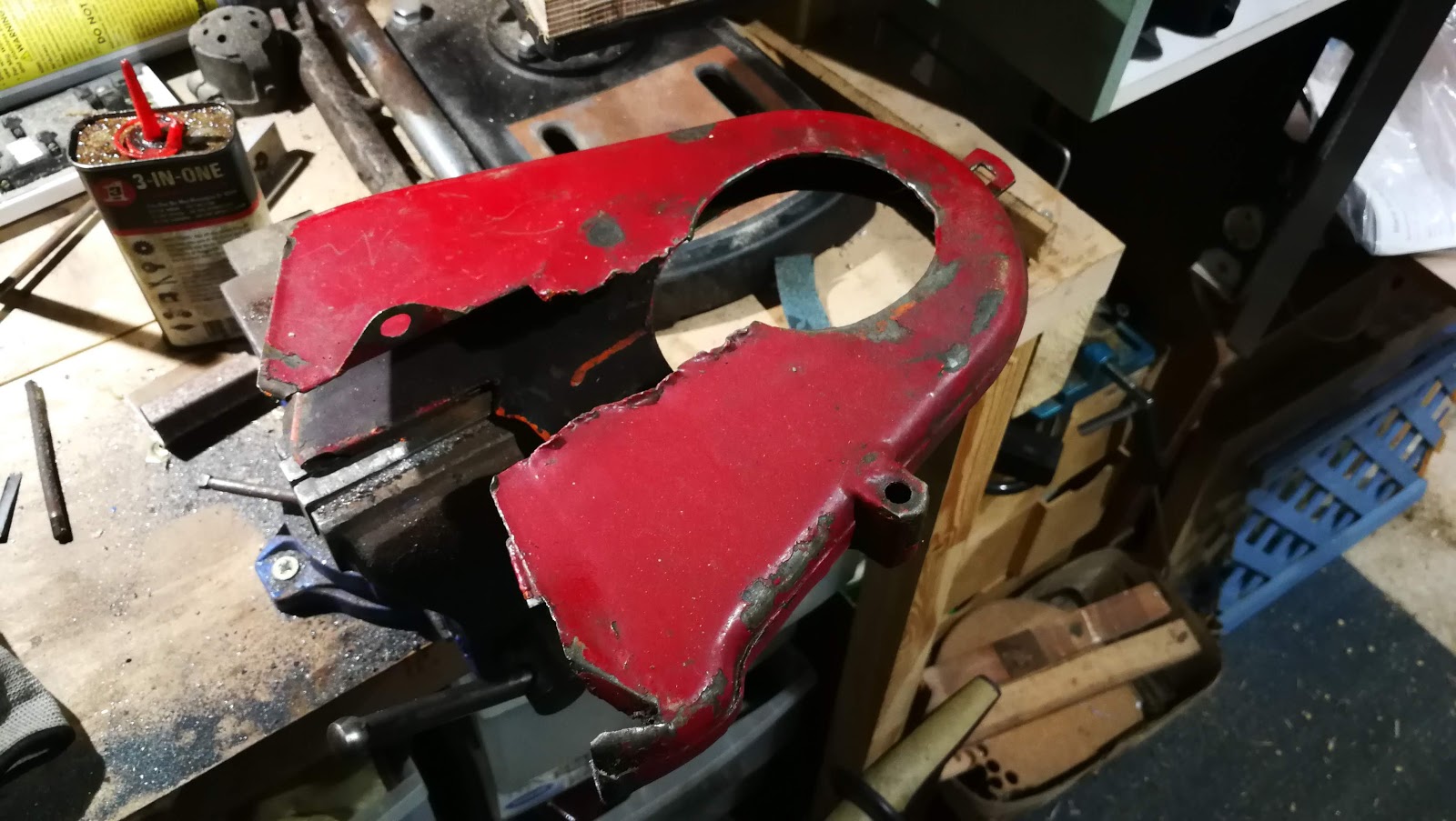
Moving on, we can start on the repair of the front section of the chain guard. This is a bit mangled:


Someone has modified it (with a tin opener) so that it can be removed without taking off the gearbox sprocket.


I don't understand this though:


This is what it is supposed to look like. These pictures are from the excellent members of the AOMCC:


You can see in this last picture, the position of the chain oiler. This is the bit that has been cut out of my mangled example, so we will need to re-create it. Mick D sent me these dimensions:


Mick says this is a 1" hole. I have the grommet from Drags:


Here's a view of the chainguard in situ - that's the chain oil pipe you can see there:


So, on to sorting it all out. Some heat and a hammer has this area flat again:


Heat and hammer again, but this activity only serves to reveal that we will have to cut this lot out:


Five minutes with a pair of aviation snips has cleaned this up. We can now find a bit of sheet to let in:


This bit will need cutting out:


Sanding off the paint allows us to measure the material thickness with the micrometer. It's 0.043", about 18 SWG or about 1 mm thick.


Now, we'll need a pattern to cut a bit of 18 SWG sheet. We can do that with a bit of paper and a pencil - we'll just draw around the other, good side to get the curve around the swinging arm, and we can use the geometry of the main shaft hole to construct the missing curve there.


The chain guard fits around the horizontal frame gusset, which is accommodated in two slots above the 'swinging arm curve'. Luckily, there is enough  metal from these slots to show us where they are.

In the end, we have this little sketch.


Now, we glue that to a sheet of 18 SWG and cut it out with snips and a file. It doesn't want to be too precise, as it needs to be 'fitted' to the job. Then, I put a 2 mm flange on the end of the repair section, around the main shaft hole to match the flange on the original part. That will make the face much more rigid.

In the next picture, the chainguard has a chunk of oak, 1" thick, stuck inside it so we can secure it in the vice. I've trued the lower edge of the cut out area with my hammer, and straightened the cut edge with a file. You'll notice the top edge is still quite bent - I will address that next. I've also messed up the flange at the bottom there, it needs to come in a bit more.


See the little blue and red crescents in the picture? For those that were wondering, they are magnets holding the repair section in place. Here's another magnet, showing the position of the grommet hole:


Ready for welding:


Butt welding with TIG in 18 swg. Set at 25 A with 5 l/min argon:


There are a few points where I need to fill holes I'd blown in it, but generally not too bad. Back side shows good penetration.


Before we go any further, we will do a trial fit and take some more pictures, to understand where the guard is near the frame and other components.


Next, we are going to mark out and cut the hole for the chain oiler grommet. The oiler pipe goes vertically down the triangular gap in the middle of this picture - the grommet position is quite critical:


Using Mick D's dimensions, we can mark out the hole. I thought I might chain drill it and file to shape, so I have used the old-fashioned witness marks around the diameter:


I've made two more repair sections for the rearmost lower edges. We will weld these in later.


I found these step drills on eBay somewhere and they seemed to get a good write up. I decided to use the biggest one to drill the grommet hole:


They make a much better job of drilling holes in sheet metal than a conventional twist drill.

A couple more hours in the workshop sees it fully welded, dressed and protected with a layer of primer.



Lathe Repair

I love my little lathe, and it sees a lot of use as regular readers of these pages will know.

Recently I've been doing a bit of thread cutting and the change wheel cover has been on and off; the control box has been on and off too, because I needed to oil the lead screw bearings. During this process I managed to break one of the wires to the speed sensor - which was hardly surprising as it is quite vulnerable:


When I removed it, I broke another:


You can see how vulnerable they are. The conductors are tiny and they are soldered directly to the sensor board, with no protection or strain relief.

Making a note of which was which, I put some 0.1" pin headers on the board, and soldered the conductors to them. The idea of using the pin headers was that they would give me something to anchor the heat shrink I'd put around the cables - the cable, heat shrink, pin header arrangement is much stronger than the direct soldered conductors used originally.


The whole thing needs potting really, but it works OK.

Wednesday, 30 March 2016

Rusty metal

While it doesn't look too bad from this angle, the battery tray on this MZ TS125 is falling apart due to acid damage. There is a crack from one of the hooks for the battery retaining strap which means that that tab, with the M5 hole for the side panel is quite floppy.


Since it was only going to cost me a few minutes, I tried to braze it up but in practice it is all too thin to have any strength, so the easiest thing to do is cut it off and make a new one. The bracket used to mount the battery tray on the frame is sound, so we can cut the tray away from it retaining as much as possible of the old tray to provide a pattern for a new one.


I have some 18 SWG cold rolled sheet in the shop, which is a good deal thicker than the original which looks like 22 SWG. You can see the extent of the damage in these pictures.


The new one is very simply folded from sheet, cut out with the jigsaw & hacksaw and with 5 mm holes drilled into the corners for clearance and drainage. We'll tack the corners together with the MIG welder.


Here's the hooks folded down and around the old strap.


So now I have transferred the side panel tab to the new tray, and brazed it in place in case I have to move it again. Next, to weld up the corners and finally weld the tray back to the frame:


Welding the outsite of corners is tricky if you are not to blow the material away completely; my welding needs a lot of dressing! Corners done, we'll tack it in place using the old one as a guide:


We'll need to fit some other parts around it to confirm that the side panel mount is in the correct location, and then we will complete those welds underneath. Removing it with those fully welded would probably destroy my new tray.


Just a little U-Pol etch primer to avoid rusting...

A few days later I have the cast aluminium rear mudguard and the coil bracket to mount up and test my new battery bracket. I'll put the lot in the vice and mount the rear end with some 10 mm pins, that are a close fit in the holes and don't allow any wobble:


You can see the three M6 mounting holes for the side panel - one in my battery bracket, one on the coil bracket and one in the mudguard. Here's the side panel mounted up:


Perfect! now we can weld up and apply some paint.


And that's it, ready to be returned to its owner.