Well, the charging system is not working. Hardly surprising after an indeterminate period of laziness under the Italian sunshine, but the problem must be in the regulator, wiring or dynamo. The wiring is very simple and it's brand new; the dynamo needs inspecting anyway and is first up.
Removing the Dynamo
The dynamo is removed by releasing the clamp holding it onto the magneto and removing a nut drawing the drive end of the dynamo into the magneto drive cover. Suspicion is immediately raised by this screw:
 |
| Conspicuously shiny and really shouldn't be there! |
There should be a little sleeve nut on a stud there. There is nothing too much wrong though - it motors when connected to a battery
View of the drive from the magneto. It was at this point I realised the whole magneto rocked slightly on the engine plates - not loosely, as though the mounting nuts were not tight, but as though something was bending.
The reason is that the fourth mounting is broken - we will have to invent a way of getting to that.
 |
| Broken 5/16" hex screw |
Dismantling the Dynamo
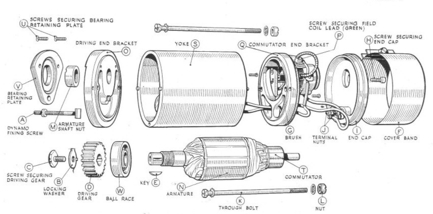
This handy diagram comes from the W/NG workshop manual.
The manual is also useful to show us how to take the dynamo to pieces.
Starting to look over the dynamo on the bench, we can see the drive end bearing retaining plate (Item V in diagram H13) is loose.
 |
| Stud and sleeve nut missing |
Removing the commutator cover band by releasing the clamp screw on the cover band (F), we find the cork gasket looks like a tired bit of cardboard. New gasket required.
Greasy brushes:
Mucky scored commutator:
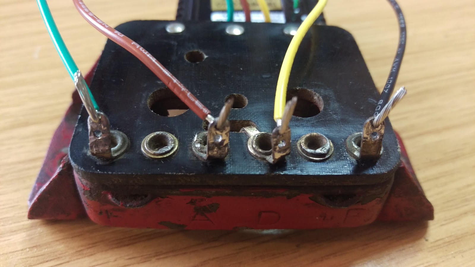
The next thing we do is remove the brass screw (H) securing the end cap (I). Next, we can remove the nuts (J) securing the D and F wires to the end cap terminals
 |
| Brass screw H back in place for safe keeping |
Next, disconnect the wiring in the commutator end of the dynamo to allow you to continue dismantling.
 |
| Disconnect the earth side with this screw |
 |
| Disconnect the D brush with this screw |
Remove the wire link between the D brush and the D terminal on the end cap.
 |
| Wire link, D brush to end cap D terminal |
Remove the brushes by pulling back their springs with a wire hook, small screwdriver or a small pair of pliers. Pull the brush out gently.
 |
| One of the brushes |
With the brushes out, you can see the commutator.
 |
| Dirty commutator |
The next job is to remove the armature. Grip the drive gear in the soft jaws and remove this screw, starting by knocking back the tab washer (if it is still there).
Sometimes the drive gear is a tight fit on the armature. Remove it with a small puller - watch out for the key:
 |
| Drive gear dismantled |
Next you can remove the two long screws (K) running through the yoke (S). Grip the nuts (L) at the commutator end as you undo the screws.
With the screws out, the armature will pull out of the yoke. I didn't expect to see this ball bearing on the commutator end.
The next step is to free the drive end bracket (O) and the drive end bearing retaining plate (V) from the armature. We'll need to remove the armature shaft nut (M) for this. This has two slots in the top and needs a special tool which I cut from a damaged box spanner:
After some filing and a dose of case hardening it is ready for use:
With the armature in the vice in soft jaws, the tools, equipped with a tommy bar makes short work of the slotted nut.
Rebuilding the Dynamo
Drive End Bearing
Someone has mangled the drive gear journal with a punch - that will clean up easily. The bearing is held in place with these screws. Unfortunately, that fine thread is a poor choice in this soft alloy and one of them has stripped. It's only 73 years old as well...
The bearing is very rough. We'll measure it up and get a new one.
Like this:
It's a double sealed bearing, so that it will retain its own grease and prevent oil coming into the dynamo.
The bearing retaining plate (V) is, as I said, loose. We'll need to repair those tiny stripped screws - I have decided to replace them with 4 BA screws which are slightly larger and will be stronger, especially as I will run the tapping size drill right through the driving end bracket (O), so the screws will be longer. Countersunk 4 BA screws will still fit in the original holes in the plate.
 |
| Recutting the drive end bearing threads |
The result is quite neat:
 |
| New 4BA csk screws in brass |
With the drive end bearing assembly complete, we can refit the armature with its nut.
 |
| Armature reassembled into the drive end bearing |
Next we need to look at the other end.
Commutator End Bearing
The commutator end is still a problem. This is the journal for the bush - the bush ID is 0.318"; this journal is 0.275" OD, which is very undersize...
The rolling bearing should not be there on an E3HM; it maybe home made - there is a journal machined in the end bracket and as previously noted, the journal for the oilite bush is undersize. The bearing is 22 mm OD;
Unfortunately, the journal diameter in the commutator end bracket (Q) is larger.
It's actually 22.5 mm ID. I'm wondering if this was meant for a 7/8" bearing, which is around 22.25 mm OD. They are cheap, and I could order a double sealed (2RS) bearing which would last a while but these bearings will be too large on the ID. Whoever modified this, and it is non-standard, ground the armature to suit the 22 mm bearing. I have no choice but to shim the journal to suit the bearing, which works fine.
I can refit the through bolts and nuts (K) and (L) and move on to the commutator. These are fitted with shakeproof washers both ends - I must remember to fit them when I find some!
Commutator
Once the bearings are sorted, the next step will be to rebuild the commutator. The first job is to thread the field coil leads through the fibre plate on the commutator end bracket (Q) and fit the plate with the three tiny screws:
I have a set of NOS Lucas 200290 brushes, all the way from Australia:
Holding the springs back, slide a brush into each holder, checking that it is free to slide. Mine are a bit tight and will need a polish. Let the free end of the spring rest on top of the brush:
Wiring Up
The link connecting the D brush to the terminal on the end cap was horrible, as shown earlier. We need a short piece of wire and a couple of small ring terminals to fix it:
 |
| Crimped and soldered |
Connecting the wires back up is simple, but it pays to be careful with the routing. Try the wiring with the end cover loose:
Its quite tight in there, and the D wire passes closed to the F terminal:
Testing
Quite the easiest way to test the dynamo, re-magnetising it in the process, is by causing it to 'motor' - that is, driving it from a battery and causing it to behave as a DC motor.
To do this, connect the D and F terminals together (I use a small crocodile clip to span the terminals - one jaw in each hole). Connect the case of the dynamo to your battery's earth terminal (negative in the case of the W/NG) and the other terminal (positive in my case) to the crocodile clip. The field coil and the armature are thus both exposed to 6V, and the dynamo should smoothly turn, relatively slowly, in the direction that it will run on your bike. In the W/NG's case this is anti-clockwise when viewed from the commutator.
End Cover
The commutator end will need a new cork gasket. The originals were riveted in place with the bifurcated rivets still remaining in this band:
I've cut some holes with a wad punch to allow the band to fit in place without removing the original rivets:
Drive Pinion
Refit the key and slide the pinion into place. The pinion is retained with a 1/4" BSF screw with an oversize shallow hex head; this is retained with a tab washer. Pimple the tab washer into one of the pinion keyways, and when the screw is tight fold up the tab washer against a flat on the hex head.
 |
| A 'before' picture of the drive pinion |
Refitting the Dynamo
Once the end cover is back on and the sleeve has been tightened down, you can refit the dynamo. Grease the magneto drive pinion by turning the engine on the decompressor, then slide the dynamo into the retaining strap. Draw the dynamo into place using the sleeve nut.
 |
| The sleeve nut whose absence started it all |
You can then tighten the strap screws with the special dynamo spanner and refit the yellow and green dynamo and field wires.
 |
| Dynamo spanner |
 |
| Dynamo & field wires |