Wednesday, 21 February 2024

SQ4 gearbox rebuild

 Now we know what we have to do, we can get started with the rebuild helped by these lovely new bushes from Geoff at AOMCC Gearbox Spares

First job is to remove the two Welch plugs over the layshaft and camshaft; I drill a hole in these and lever them out:


With some heat in the casting, you can drift the layshaft and camshaft bushes out from the drive side:


The sleeve gear bushes come out with a bit of tube; the new ones go in with a large flat drift. They go in quite easily with a hammer (you don't hit the bush directly), but it's times like this that I wish I had a press.


The new drive side bushes can be pulled in with suitable studs and washers:


You need to be careful with the layshaft bush. It's easy to get it misaligned, and there is an anti rotation pin designed to keep the grease groove at the top. At the factory this was drilled and fitted from the drive side, but with a replacement bush you must align the slot in the bush when you put it in.


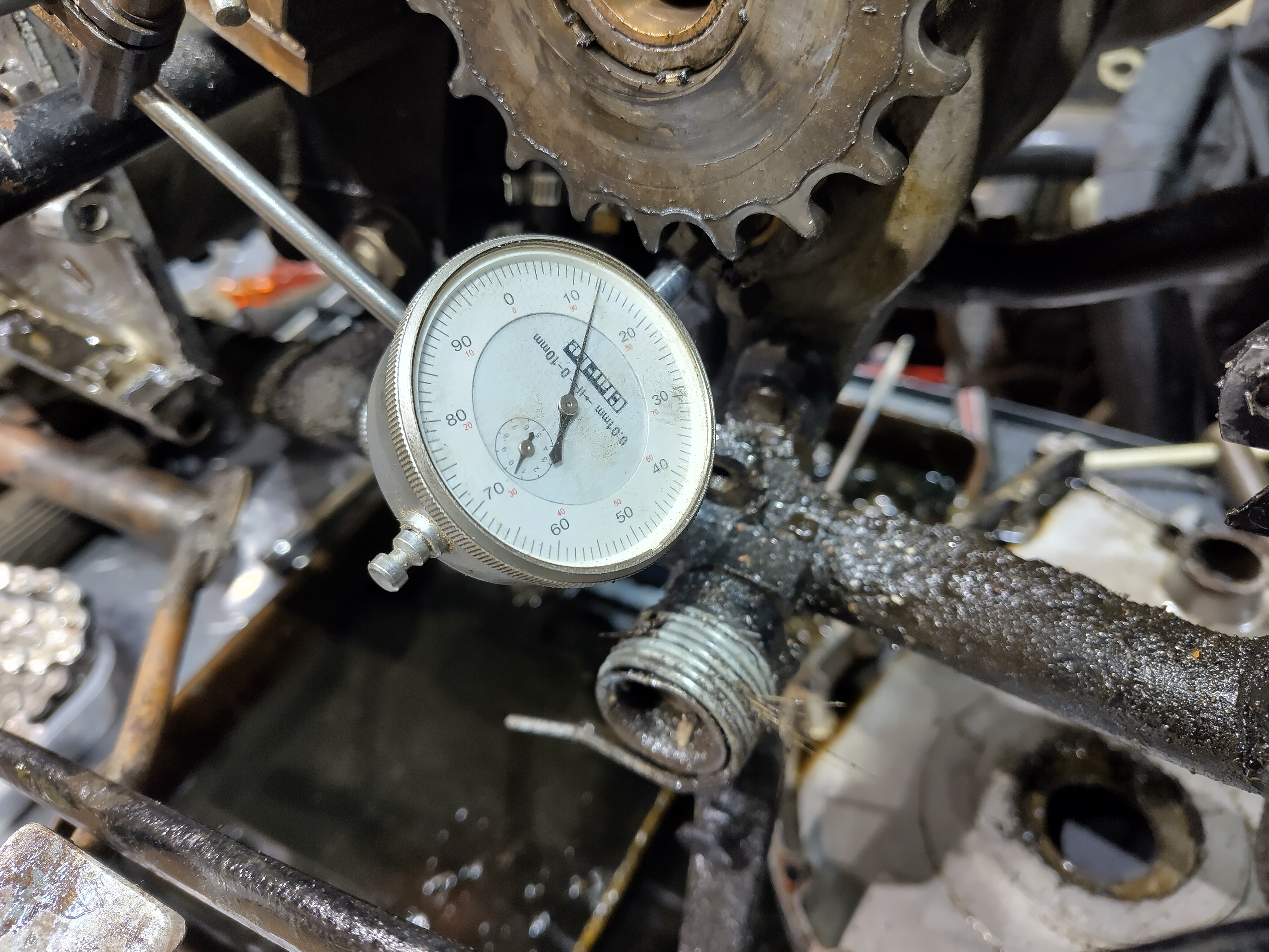
All this work culminated in 0.13 mm end float (5 thou) on the layshaft. That's better than the 9 thou I had earlier, and I have the proper gasket fitted now.


What's not so good is the 0.37 mm I have on the camshaft. That's about 15 thou and will have to be sorted with shims.


I've also decided to discard these two nuts and make some new ones. The threads are poor and the nuts would be better twice that thickness.


We'll fix the camshaft end float with this 0.3 mm shim. It's a commercially available 26 mm ID shim that I've opened out to fit:


This shim fits inside the inner cover. Unfortunately, I found out later that this is a 0.5 mm shim in a wrongly-labelled bag - testing revealed a selector shaft that was firmly clamped in place.


Here's the selector shaft assembled and greased ready to go in.

A trial fit, with shakeproof washers under the BSW nuts (to prevent them coming loose) revealed the shim problem. I went through two bags of shims with a micrometer and found that all the shims in the 0.5 mm bag were 0.3 mm and all the ones in the 0.3 mm bag were 0.5 mm...

Easily found and fixed, fortunately. It pays to measure and test at every step. 

With that fixed and the selector shaft showing about 0.05 - 0.07 mm (2 thou or so) end float we can set up to measure the mainshaft and sleeve gear end floats.

The mainshaft endfloat still measures 0.88 mm or 35 thou: not surprising, since we haven't changed anything.

The sleeve gear shows 1.11 mm when in top gear:


A call to AOMCC gearbox guru Geoff suggested I make a spacer to reduce that to 0.11 mm, 4 thou, to maximise spline engagement. Geoff provided a useful spacer to make that from:
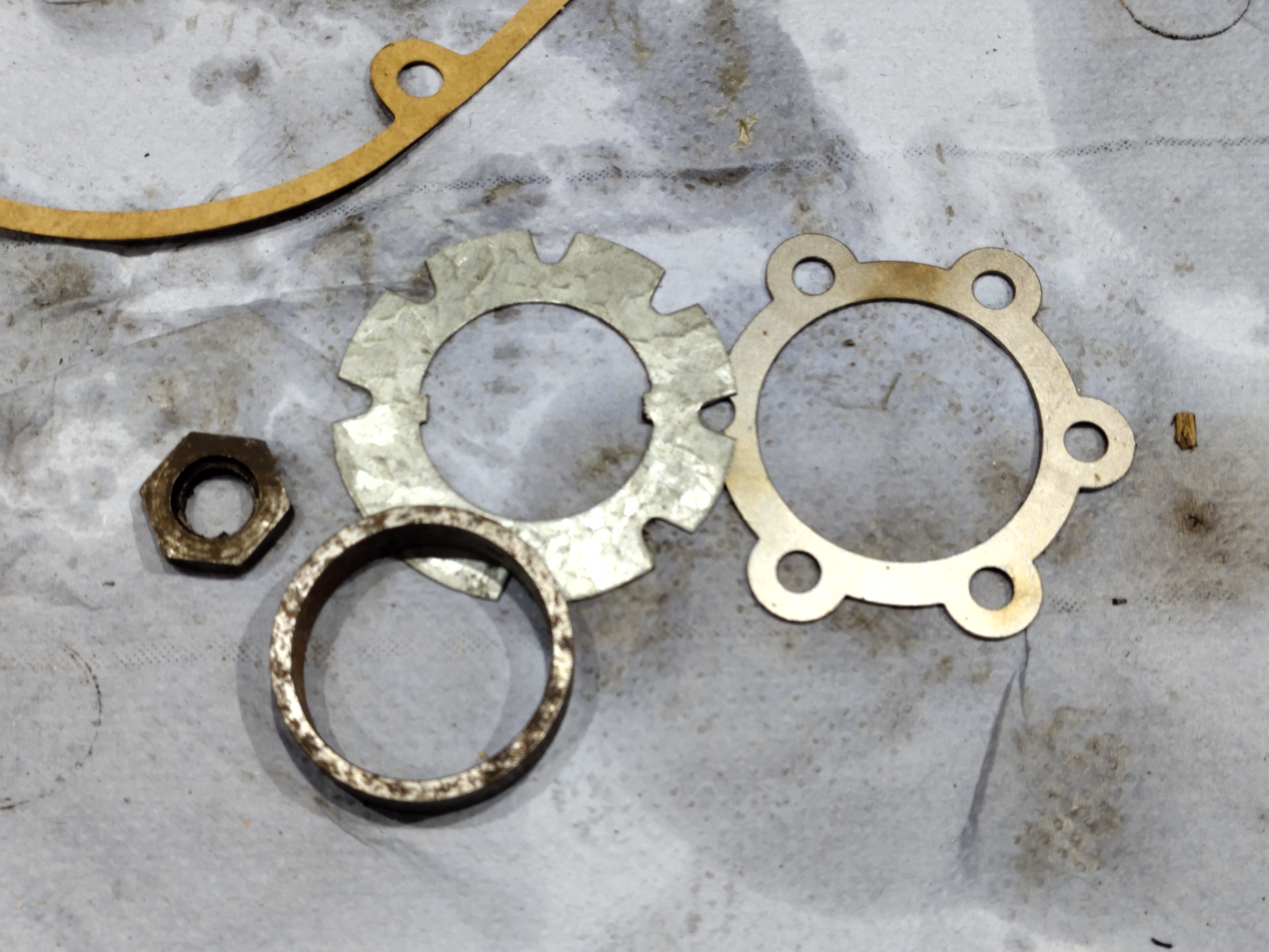
This is the spacer that sits under the gearbox sprocket, inside the oil seal. It parts off quite easily on the mini-lathe, once you remember that you don't want the lathe in high gear!


The spacer fits neatly on the inside of the main sleeve gear bearing, pushing the sleeve gear splines into further engagement with the mainshaft sliding gear splines.


To deal with the excess mainshaft end float, I have machined a 0.5 mm recess into the mating side of the nut. This will restrict mainshaft travel a little more and should bring the end float down to somewhere near 0.38 mm, or about 1/64".


Reassembling the gearbox reveals sleeve gear movement at 0.8 mm; I must have measured that wrongly as I thought I had 1.11 mm and added a 0.75 mm spacer. Mainshaft end float is now 0.6 mm, down from 0.88 mm and around 25 thou. This is 1/40", within Ariel's stipulated range of 1/64" - 1/32".

All good news; however, since tightening the inner case nuts for what I thought was the last time, I've realised that the camshaft is too tight. It turns, but that 2 thou end float has clearly been taken up by gasket compression - I may relieve the bush a little or I may fit shims to 0.2 mm (8 thou) rather than the 0.3 mm currently fitted (12 thou) which should give me what I need.

As it turned out, smoothing the surface of the camshaft bush was all that was required to return to normal operation, so I tightened up the end cover. The last step was to fit the two Welch plugs, which have to be done before the sprocket goes on for the last time. It would have paid to ensure the bores for these were clean before the bushes went in, as enthusiastic staking at the factory had left a lot of material in the layshaft bush bore which had to be scraped out with a twist drill ground flat, like an end mill.


Next job is to close up the other end of the gearbox, but I can't do that without the clutch in place as I can't hold the mainshaft to do the nut up on my own.


More next time.

Friday, 2 February 2024

SQ4 Gearbox Investigation

Starting the Square Four up mid winter is something I do at least once a week just to make sure it's all working, which it usually is - except when it isn't.

This week I was met with an unexpected noise, like gear-dogs clashing - it sounds like it does when you put it into first gear. Listen to the sound, especially obvious around 28 seconds:


The noise stops as you disengage the clutch (which is dragging badly) as the mainshaft slows to a stop. It's also not present if you run the bike in gear on the rear stand.

Casting to the forum & FB world for advice, I ended up having a chat with AOMCC gearbox guru Geoff - 30 minutes of good advice. To summarise:

  • Poor Sleeve gear position leads to dropping out of top gear. It seems I might need an extra spacer to move the sleeve gear towards the mainshaft sliding gear
  • Minimise Layshaft end float, centralise in new bushes
  • Minimise Camshaft end float
  • All the bits are available from AOMCC Gearbox Spares, no bushes need reaming 
Here's the gearbox drawing, for reference:


So on with the work; first job is to get the bike on the lift. This entailed fitting the centre stand springs to the FH, which is a story in itself. Having the half-built FH on the bench is quite a different experience to having the SQ4 up there - you realise how heavy it is, but the lift is quite happy and accommodates the rear stand quite well.


Yet again the bench proves it's worth, supplemented by the new lights overhead. I bought some strip lights to add to the interior light circuit, and when I put them up I moved the old interior lights, which used to face the benches, to face the bike on the lift. Then benches are taken care of by their own circuit, and now I have both sides of the bike illuminated.

Removing the outer cover reveals no issues with the selector or kickstart. I must remember that this box is missing it's kickstart rebound rubber if I recall correctly.


I set up the DTI on the lift deck. This isn't ideal, as it reveals the bike is swaying about a little on it's stand but the arrangement serves to reveal 1 mm end float on the mainshaft, 0.3 mm on the layshaft and 0.3 mm on the selector shaft. The limit specified in Waller for the mainshaft is 1/32", which is about 0.8 mm. There's nothing specified for the other two shafts.


You might recall some issues we were having with the clutch towards the end of last season - I wrote them up here in a post called Clutch Investigation. The end float in the mainshaft possibly contributed towards this problem.

We'll move to the other side now; the first discovery is no surprise - the clutch centre nut has backed off again, though the tab washer prevents it moving too far. The reason for this is the splines, which are very worn and won't take any load without moving a little:


This is a new AOMCC clutch centre. The splines are wider and have square shoulders:


With the clutch off, I was able to get a better quality mainshaft endfloat measurement of 0.88 mm (35 thou) with the DTI magnetic base mounted on the engine/gearbox plate


Moving the DTI to a steel plate clamped to the gearbox produced some better numbers for the layshaft and camshaft:


In summary, I have end floats as follows:
  • 35 thou on the mainshaft, a bit over 1/32”. Ariel's stated limits are 1/64" - 1/32"
  • 9 thou on the layshaft. Ariel only state a minimum for this end float.
  • 9-10 thou on the selector. Ariel only state a minimum for this end float.
So, barring the sleeve gear, I have it all apart and can measure up. The parts washer is such a useful piece of equipment.


In no particular order, here are some pictures. Having stripped the gearbox I have discussed it with various experts on the AOMCC forum and Facebook pages, and twice with Geoff, the AOMCC gearbox spares specialist. These are the two selector pins - the wear is obvious, but not measurable. These are not going to be changed.
 

This is layshaft 2nd; dogs are good, teeth are good.


This is the layshaft sliding 'clutch' - dogs are good, splines are good.


This is mainshaft 3rd; dogs are good, teeth are good.


Selector forks are a little worn but show no sign of bending, burning or major damage. They are a good fit in the grooves on the sliding sleeves.


Two things in this picture - the sleeve gear, which I can't remove yet (big box spanner on the way) and the drive side layshaft bush. The shiny ring shows you where the layshaft output gear has passed it's end load.


The dimensional survey revealed the following: 
  • Layshaft 2nd gear bush 1.061” gear 1.065” 4 thou clearance
  • Layshaft 1st gear bush 1.062” gear 1.0653” 3.3 thou clearance
  • Mainshaft 3rd shaft journal 0.786” gear 0.788” 2 thou clearance
  • Sleeve gear bearings: 
    • Mainshaft outer journal 0.931” sleeve gear bush 0.940” 9 thou clearance
    • Mainshaft inner  journal 0.928” sleeve gear bush 0.941” 13 thou clearance
  • Kickstart pawl bush length 0.81”
  • Layshaft timing side bush 0.663” shaft journal 0.652”, 11 thou clearance
  • For some reason I didn't record the dimensions of the layshaft drive side bush or the camshaft bush, but I guess I had already committed to changing them because of the end float. Well, that's the best excuse I have right now.
And another one from the experts - it looks like the timing side mainshaft nut is wrong, as it doesn't bear on the kickstart pawl at all.

So that's it! New layshaft, camshaft and sleeve gear bearings and a new kickstart rebound rubber.

Friday, 12 January 2024

FH - centre stand springs

I'd been dreading this job, but needs must. I was forced to face up to it because I needed to get the Square Four on the lift in order to look at the gearbox before the riding season begins, and I didn't want to resort to holding the stand up with an aerolastic.

The way I did this was to take a piece of 2" rolled angle and drill a 6 mm hole at one end; I put a long M6 screw in the hole, and the small eye of the stand spring over the screw. Then I took a bit of 1/2" round bar and used it to stretch the spring by levering it against the end of the vice; I put a 5/16" washer in each of the gaps between the wire coils and when the spring was relaxed it was long enough to push into place by hand. All I had to do then was move the stand to stretch the spring again and all the washers fell out. 

Repeat for the second spring and we are done.


First time outside on it's wheels:

Even my wife says it looks lovely.

Thursday, 11 January 2024

FH - Jeff Hunter Engineering

 I've written about the value of the specialist suppliers before, in various media. As you know and can read in this blog I make a lot of (unobtainable) parts myself but we really must keep the specialist suppliers in business, particularly the ones that are making high quality stuff. I was speaking to one only this morning and they are really not making massive profits so we must support them and not dilute their market.

Without people like Acme, Draganfly, the AOMCC and several others, we'd have a lot of unrideable museum pieces.

Here's another example - Jeff Hunter Engineering, a.k.a 'The Rubberman'. I've got all the rubber parts for the FH, the W/NG and the Model A from Jeff. Here's a couple of examples:

Tank rubbers

Centre stand bump stop

Saturday, 16 December 2023

FH - Engine breather

 The engine breather on the FH is similar to that on the BSA A10 & A7 and is comprised of a timed vent driven by the idler wheel in the timing chest, ported through the crankcase joint behind the camshaft space to an outlet ahead of the gearbox sprocket.  There’s a little copper pipe which arrived like this:


It’s not supposed to look like that. It’s supposed to be like this:


In the days before the FERC arrived, this pipe was led to a gap in the alloy arc cast on the back of the primary case to protect the gearbox sprocket, so anything coming from the breather lubricated the chain. When the FERC arrived, the breather pipe didn’t change as far as I can tell but as you can see it can’t get to the gearbox sprocket any more.

We’ll direct it downwards.

First step is to anneal it by heating it cherry red and quenching in water:


I want a bend, just less than 90° to direct the gases downwards. I use the little pipe bender to make a tidy job of that:


I added a bit of 8 mm fuel pipe to a level fractionally below the lower frame rail. 


That will do nicely.

Monday, 11 December 2023

Solex Idle Circuit

I've known for some time that I didn't have a drawing of the Solex 26 AHD on the blog. Today, coincidentally, someone was asking about the jet locations and problems with idling on the AOMCC Forum. I uploaded a drawing and Pete Silson provided some wise words, and an annotated the drawing to suit. Before we get to that, note that the fuel follows the orange highlighted path before it reaches the pilot air bleed jet, when the blue mixture path begins:

I don't believe the notch under the choke tube has any effect on tick-over. The four usual sites for blockage of the pilot mixture path are shown in the diagram below.


Air leaks anywhere in the mixture path (blue in diagram) cause erratic tickover. Blockage of the pilot jet (3) weakens the tickover mix, blockage of the pilot air bleed (4) richens the tickover mix. There are two small holes either side of the butterfly (1 & 2) which can also get gummed up - the size of these are important so best to blow them through with air rather than poking with wire.

The tickover mixture is governed by the ratio of the Pilot Jet 070 (0.7mm) and Pilot Air Bleed 150 (1.5mm). The tickover mixture is further adjustable using the Volume Control Screw - clockwise for weaker, anti-clockwise for richer. The tickover speed is adjusted by the throttle stop on the main butterfly.

The ratio of the Air Correction Jet and the Main Jet and the Emulsion Tube controls the mixture over the whole rev range. The Air Correction Jet has more influence at higher revs.

The jets are illustrated in this post. Apparently Mikuni were agents for Solex at one time and Mikuni jets fit these carburetters.

Sunday, 10 December 2023

FH - bottom end complete

A little bit later than expected I am back in the workshop. My generator decided to burn out it's alternator winding, and took the battery charger with it which meant buying a new generator, building a trolley for it (it doesn't fit where the old one was) and building a trolley for the welders - because their spot is now taken up by the generator...

Having got most of that out of the way, I can strip the cases again to fit the replacement connector rod nuts, BSA part number 37-1691. These are genuine new old stock from Vale-Onslow. Looking at the picture below, from left to right we have the modified Draganfly nut, an unmodified nut, and on the right the new lower profile nut:


This, by the way, is the mark left by the Draganfly nuts before I modified them:


Here are the Draganfly big end bolt washers. These are laser cut stainless and whilst some suggested they were rather small, they are much the same size as the bearing surface of the nut so I am leaving them in place.


Stupidly, I forgot to picture the new nuts in place on the big end caps. Mrs H phoned to see where I had got to (I'll just be 10 minutes dear!), and that's always a distraction. Suffice to say that they were torqued up to 22 lbf. ft in accordance with the BSA data sheet and I oiled up the various bearings before closing the cases. I made sure to remove all traces of Threebond and was very sparing with it when reassembling.

The case bolts are all stainless, from Acme as usual and they fit beautifully. I made this chart from the diagram in the Draganfly catalogue to show me where the different bolts go:


Lovely and easy putting them in; I used my frame spreader to make it a bit easier.


Now that the bottom end is in, we've got a number of workfaces to tackle:
  • the barrel and pistons
  • the primary case
  • the timing gear
We can look at any of these really but before we do there are some components around the engine that will become less accessible as we progress. The first of these is the engine breather shown here in the form in which it arrived:


This isn't how Ariel designed it. It's supposed to bend around and appear behind the FERC, above the gearbox sprocket somewhere.

Another item is the magneto. It's fitted here temporarily with the long bottom nut, which is on the job list for zinc plating. With the primary case loosely bolted in place you can see that it's quite restricted in there:


Something that surprised me, and thanks to Daniel Rix on the FH Facebook page for this, is that you cannot get the brake bell crank on with the primary case in place. That's a pain, because I want to get on with the mechanical build and I hadn't planned on doing any plating just yet... and the bell crank needs plating.

The other thing I must remember is to fit the oil lines before I fit the primary cases! Access will be a trifle difficult if I forget, so let's not get ahead of ourselves and we will get on with sorting out some of the details.