Tuesday, 27 April 2021

QR50 - Exhaust & Silencer

Updated: first published November 2020

There's been a lot of sheet metal work on this bike - the magneto cover, the faux swinging arm and the silencer which was completely missing. It's one of those pressed sheet metal affairs quite widely used in the 70s and 80s on bikes when it can be hidden and some (think the last BSA and Triumph unit singles) where it cannot.

Here's one from eBay:


It's got an integral exhaust pipe, the only part of it I had left, and a separate tail pipe which looks like this and mounts in the and of the silencer. see how long it is?

It appears in the parts book like this. I haven't got those perforated guards either:


Now, these come up on eBay from time to time but at over £100 a go I was never going to buy a new one, or even a second hand one but I have a welder, a bandsaw, a brain and a calculator and making one couldn't be too hard could it? Of course, because it was entirely missing I had little idea of scale so I took this library picture and scaled off it:


You can get some idea of the thickness from the diameter of the tailpipe. I made a cardboard template for the sides, with an allowance for the curved edges:


I started to make a model from the template, to mock it up and work out how to form some of the details, like the spherical corners:


Try as I might, I couldn't see what Honda had built into their silencer but I did know that the exhaust gas went in at the front end and that the tailpipe was long enough reach to the front, so the gases must be led around various chambers inside. The formed ridges obvious from the outside of the original silencers seemed to confirm this, so I used my template to work out a series of chambers and modelled them mathematically. I found the calculations online at https://www.glue-it.com/wp/knowledge/exhaust-silencer-design/ and built a simple spreadsheet to calculate what a silencer would do at various engine speeds.


Here's the equation for one of the silencer/pipe combinations:


The resonant frequency fn for the chamber is calculated as :


Where C is the speed of sound and Lc is the length of the chamber. I plotted the results of the calculations:


From a rough sketch, I built a cardboard mockup. I started with the inner shell, and built the divisions into it:


The tailpipe needs a large tube to receive it:


The silencer is supported by the exhaust pipe and the bracket at the front. The pipe will be welded into the shell and have a brace inside:


The complete internal layout:


Here's the model with the outer shell added, fitted to the bike to determine the shape and hole positions for the bracket:


Now that the model has proven the fit of the silencer, we can use it to start on the build 'in the metal'. What I have done here is use the template again to transfer the shape onto the two sheets that will form the inner and outer shells. I've used spray paint to transfer the shape:


I've used the model to mark out a piece of thicker sheet for the bracket:


Using a couple of short lengths of scaffold pole, I have started rolling the edges of the inner shell. Here, it is held onto the bracket with magnets:


Using the same technique as that used on the cardboard model, I have split the hemispherical corners ready for bedning:


I closed them up around the same scaffold pole, so the radii are correct:


Welded and painted:


When all the corners are done, we can cut the dividers using the bandsaw, linisher and some cone drills. They are set up temporarily with welding magnets:


There will be a fourth piece which will be used to reinforce the exhaust pipe as it enters the silancer:


The tubing is just cheap 19 mm ERW steel tube. In a former life it was a curtain pole.


The tail pipe needs a mounting tube welded in the shell. This needs to fit tightly around the tailpipe, so I will roll it up from sheet:


The original tailpipe features a frustrum at one end. I've used the model to transfer the shape to a bit of sheet, which we can roll up using a hammer and a small mandrel:


Here are the pieces of the tailpipe and it's mounting tube:


Tacking up the tailpipe:


We need to assemble the silencer to locate the tailpipe in the right place, prior to tacking in the mounting tube:


With that done, we can have a look at the tube arrangement inside prior to welding it up. 


The location of the incoming exhaust pipe and its bracing plate are key to the internal tubing location, so we will have to put some time into that. I had considered making a die and hot forming the tube, but a few experiments showed that the bend needed would be too tight to successfully form by that method, so I decided to mitre & weld the bend instead:


Here's the tube in position. I used this set up to mark the position of the brace inside the shell with a Sharpie.


Knowing the position of the brace I could tack in the internal tubes into the dividers:


You see the position of the brace in this shot. The tube from the front chamber to the rear is tacked in all three dividers in this shot, and I am setting up the tube between the two middle chambers:


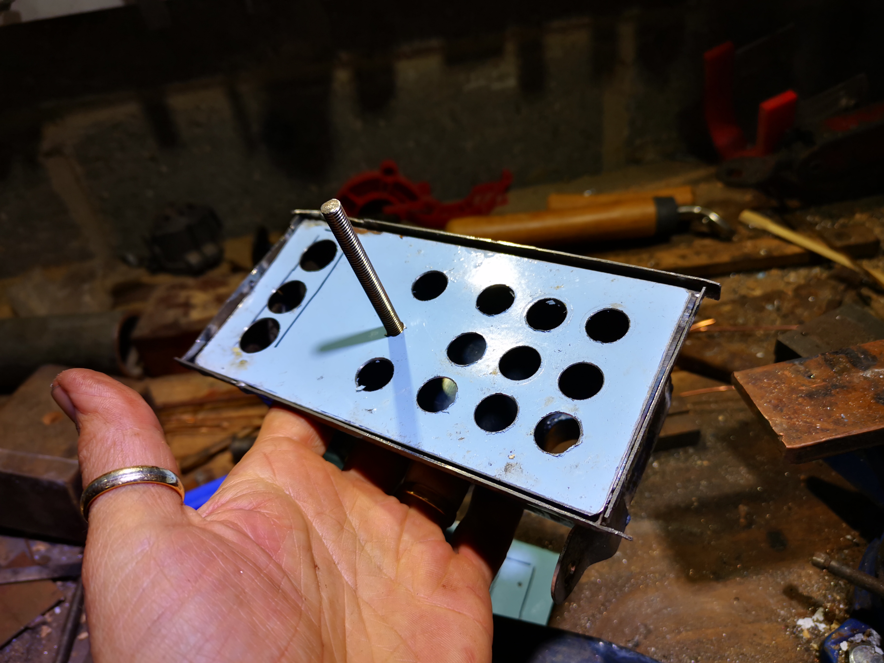
This shows all the tubes tacked in. The empty holes in the dividers are for the tail pipe.


Next step is to get ready to weld the bracket on. The bracket will have five plug welds and four fillets' the Dykem marking blue is to mark the radii prior to linishing and welding the double sheet.


The whole silencer assembly is fitted (yet again) to determine the final position of the incoming pipe and it's brace. Whilst the internal assembly is tacked together, it is held in the shell with magnets at this stage.


Here's the incoming pipe, trimmed a little and with the brace in plate. I've introdcued another small plate to provide some flexibility around the position of the pipe as it passes through the shell:


Here's the assembly tacked together and in place in the shell - it's not in the right place - something must have slipped during clamping...


With that last element in, we can replace the baffle and tube assembly and put the two shells together. I should have allowed considerably more (spare) material since for some reason there is a gap at the bottom. I'll make a 1/2" wide strip to go all the way around the seam.


I've now tacked the shells to the baffles and to each other:


These two images are from eBay - someone is selling laser cut heat shields for these exhausts but unfortunately they are in aluminium. I will have to make my own as I want them in steel - they won't last five minutes in ally, before they are bent out of shape.


Here we go. I cut the shape from a bit of 0.9 mm cold rolled sheet using aviation snips and started to raise the edges on a dolly:


I worked the edge up gradually:


Until I had the shape I wanted. I trimmed out parts of this raised edge to let the pipe pass underneath:


I also reduced the height a little using the linisher, and cut some holes with a cone drill:


The heat shield is held to the pipe with a couple of M5 screws. These go into weld nuts I fitted:


Sunday, 25 April 2021

QR50 - seat overhaul

I hadn't intended to do anything to the QR50 seat, but as the rebuild progressed the seat became the part that let it down - and it occurred to me that I had not recovered a seat for a long time. I had a bit of vinyl knocking around from the FH tool roll, so there was no excuse really...

Here's the seat after I finished scrubbing the red paint off it:


Here's a view of the underside:


The cover is stapled into the moulded seat base, and the staples come out quite easily. Here's the cover, made in 1988:


And that's it. The base and foam are useable, so we will make a new cover:


The seat has a couple of fabricated pieces that prevent the rider's legs pushing the plastic 'skirt' into contact with the exhaust. I made these from some 1.6 mm sheet and a few pieces of 5 mm rod from an old linen drier:

These bolt to the seat base.

To recover the foam, I started by warming the vinyl - actually I did the work at home with the central heating on. With a piece roughly cut to size, I started to fold the cover around the foam retaining it on the edges with bulldog clips:


The temporary bulldog clips help me understand where I was going to have to pull the cover into place, and once I was confident with this I could start stapling:


I stapled away from the centre gradually, making sure the cover was taught and sitting in the right place:


Once I was confident I had enough staples in place for the seat to be kid-proof, I trimmed away the excess cover material and assembled the skirt:


This is an older picture showing those protective pieces & how they protect the plastic from the exhaust:


Wednesday, 7 April 2021

QR50 - engine top end

One of the things that was apparent from the beginning that the piston needed replacement, as there was a large crack in the skirt. I measured up the bore and determined that the bike was still on the standard bore, and bought a new piston assembly from ebay - new rings, circlips, piston and pin:


Fitting wire circlips is always a bit traumatic. I did lose this one, found it again, and fitted it successfully the second time:


I resprayed the barrel with B&Q barbeque paint, as I used on the exhaust. We'll see how that turns out!


The original head had a lot of fins missing. This one came from eBay:


Sunday, 4 April 2021

QR50 - Fabricating the Airbox

Building a replica airbox seems like overkill for a little motocross bike that's going to be worth a few hundred quid when done, doesn't it. The original plan was to use a cheapo Chinese pod filter on the carburetter intake, £6 max and you are done, and maybe put a toolbox in the airbox space. However, as usual my OCD took over and fuelled by the fact that the carburetter moves relative to the frame and a pod filter wouldn't fit in the space available without an elbow, and then it would need support... you see how the job grows. I elected to fabricate the airbox along the lines of the original - then I'd have support, the space filled, an air filter, no cash outlay and something that could accommodate the carburetter moving up and down. Plus, I'd have more experience to help when I came to manufacture the toolboxes for the 1930 Ariel Model A.

So, out with the cardboard to make a model, the beginning of a lot of my fabrication jobs. Cardboard is great - you can make an airbox, cut it where it doesn't fit, take it apart, make a better one and eventually you end up with one that fits, like this one:


Here it is in situ:


The next step is to cut it apart again and make the net - the pattern that will be used to make the part in steel. I like to use these magnets to hold the net on the piece of sheet - this is 0.9 mm thick cold rolled sheet, part of an old bread bin.


You can use the bandsaw to cut this stuff easily, though some of the internal features need a file. It's important to deburr and to file your corners square before you start folding:


First job, cut the hole for the air outlet. Normally, it's better to cut holes after bending when the hole is near a fold, because the bending the sheet will stretch the hole out of shape. In this case, I wanted to corner weld the tube in from inside, so the hole had to be cut and the weld completed before the sides were folded up. It's critical to plan the process to make the folds as easy as possible - it is all too easy to make one fold only to realise you have prevented yourself getting access to make the next one.

I always drill holes using cone drills - it's much easier to get a circular hole in sheet metal than using a twist drill.


The air goes into the carburetter through a 1" tube, welded into the box:


The most complex fold is this curve - it's there to go around the frame. I made it round a bit of scaffold pole and when it was almost there I folded up the sides to make sure it was the right shape


In case you were wondering, I burnt the blue powder coat off...


At this stage, I welded up the edges of the curve, before I made the next folds - to ensure the material would stay in place while I subjected it to more bending. This picture shows most of the bends complete and welded:


Here, I've folded up the flanged edges and tacked on the lower mounting bracket. The tube going to the carburetter has been trimmed to length:


This is the lid, made in a similar way:


Back to the airbox again, this blue panel supports the foam:


Here's the other side, showing the inlet to the airbox which shields the oil line banjo and ensures the air inlet is protected from flapping trousers:


View from the front. That nut is attached to a stud that passes right through the lid, filter element and box and is welded into the back of the box:


Next I spent half an hour tidying up some welds - I used the linisher, some files and a small wheel in the Dremel just to smooth it out before painting. It's not perfect - I'm not spending hundreds of hours ironing out every nick and scratch but we will tidy up the worst of it. So next it's paint, starting as usual with U-POL etch primer.


Here's the completed airbox, coated in U-POL satin matt black. The parts are held together with hot melt adhesive and the element is hand cut from a piece of open cell foam:


Here it is in situ, from the top. I had to change the top bracket since it wasn't sitting square in the frame


Thursday, 18 March 2021

Model A - repairing threads

It's a wet day here in Norfolk, and I have some domestic stuff to do in the workshop so while I'm at it I might get distracted...

I'm looking at the workshop layout with a view to getting a bike lift in there, so I have shuffled them around and the Model A happens to be accessible, so we will have a look at a couple of loose ends. The front mudguard has been hanging off for a while (and still is) because there are a couple of dubious threads in the forks - one, a broken bolt, and then two other threads that are just fouled.

Here's the broken one - I have put a 1/8" hole through this broken 1/4" bolt, to see if it will come out with an Easy-Out. They never do, but I have to drill the hole anyway!


Of course, it didn't come out and I moved through the drills until I was one size under tapping size for 1/4" CEI. I then applied the 1/4" CEI taper tap and used it to clear the thread - it moved the remains of the bolt:


Next stop, same problem at the back. I made the mudguard & rack fasteners a while ago and could only fit one side, because I found someone had broken one of the 3/8" bolts in the frame lug, drilled and tapped it something like 5/16" and put a new bolt in. Today, I removed the broken 3/8" stump using a diamond burr in the Dremel and chasing out with a 3/8" CEI taper tap, so this shot shows it all back together with the stand spring fitted at last:


I also took the opportunity to chase out the chain adjuster threads. Grovelling about on the floor makes me realise that a hydraulic lift would be a nice addition to the workshop!

Back at the front, I now have both sides of the mudguard stay fitted - to cut the mudguard, I need the centre bracket and the front stand fitting - unfortunately I have run out of 5/16" screws, so that's the next job.


Comparing the next picture with my picture above, you can see I have the mudguard stay too far forward:


Friday, 5 March 2021

W/NG: finally fixed?

Since the last time I wrote about the W/NG, we have been locked down again and are only now seeing the light at the end of the tunnel. We've had snow, freezing winds, and Christmas, if only for a day or two. It's had very few outings since the COVID crisis is a very bad time to be needing the services of A&E in a hurry should the worst happen so I have been painting (a house), making an airbox for the QR50 and turning parts for the Model A

However, painting a city centre house means you need to get there and park, which is much easier on a bike so I have used it a couple of times. You might recall I put an old Lodge HN in it, to see how a traditional plug would behave - well, it failed after 200 yards and a new W8AC went in. This was fine for the rest of the commute, testing the new main jet, but the high speed thrash along the main road had us arrive back coughing, spluttering and sooting up.

Back to square one. I decided to replace the float needle, which was an old one:


Can't see what's wrong with it? No, that's because it's hardly worn. The fuel level was quite high:


Messing about with the float bowl got the level down a lot:


It ticks over nicely:


I wasn't convinced that it would make the difference, and looked back over some old pictures only to realise that the throttle needle was not, in fact new... I bought another and made a comparison:


Here, I've marked the old needle (bottom) and the new needle (top) every 10 mm. The chart below shows the diameter at each position in thousandths of an inch, with the difference in the 'wear' column on the right.


When you consider that the needle jets are sold in increments of one thousandth of an inch, wear of up to six thou' in the needle is very significant.

It has to be said, this is a schoolboy error if ever there was one - I should have bought a new needle at the outset, I would have saved a fortune in spark plugs.

A 50 mph thrash down to Weybourne produced this colour in an old B5HS.


And the fuel level? I'd set the float so low that the valve could hardly open. I could ride a couple of hundred yards and then it would splutter to a halt, and I would have to wait while the float bowl filled up again!