Building a replica airbox seems like overkill for a little motocross bike that's going to be worth a few hundred quid when done, doesn't it. The original plan was to use a cheapo Chinese pod filter on the carburetter intake, £6 max and you are done, and maybe put a toolbox in the airbox space. However, as usual my OCD took over and fuelled by the fact that the carburetter moves relative to the frame and a pod filter wouldn't fit in the space available without an elbow, and then it would need support... you see how the job grows. I elected to fabricate the airbox along the lines of the original - then I'd have support, the space filled, an air filter, no cash outlay and something that could accommodate the carburetter moving up and down. Plus, I'd have more experience to help when I came to manufacture the toolboxes for the 1930 Ariel Model A.
So, out with the cardboard to make a model, the beginning of a lot of my fabrication jobs. Cardboard is great - you can make an airbox, cut it where it doesn't fit, take it apart, make a better one and eventually you end up with one that fits, like this one:
Here it is in situ:
The next step is to cut it apart again and make the net - the pattern that will be used to make the part in steel. I like to use these magnets to hold the net on the piece of sheet - this is 0.9 mm thick cold rolled sheet, part of an old bread bin.
You can use the bandsaw to cut this stuff easily, though some of the internal features need a file. It's important to deburr and to file your corners square before you start folding:
First job, cut the hole for the air outlet. Normally, it's better to cut holes after bending when the hole is near a fold, because the bending the sheet will stretch the hole out of shape. In this case, I wanted to corner weld the tube in from inside, so the hole had to be cut and the weld completed before the sides were folded up. It's critical to plan the process to make the folds as easy as possible - it is all too easy to make one fold only to realise you have prevented yourself getting access to make the next one.
I always drill holes using cone drills - it's much easier to get a circular hole in sheet metal than using a twist drill.
The air goes into the carburetter through a 1" tube, welded into the box:
The most complex fold is this curve - it's there to go around the frame. I made it round a bit of scaffold pole and when it was almost there I folded up the sides to make sure it was the right shape
In case you were wondering, I burnt the blue powder coat off...
At this stage, I welded up the edges of the curve, before I made the next folds - to ensure the material would stay in place while I subjected it to more bending. This picture shows most of the bends complete and welded:
Here, I've folded up the flanged edges and tacked on the lower mounting bracket. The tube going to the carburetter has been trimmed to length:
This is the lid, made in a similar way:
Back to the airbox again, this blue panel supports the foam:
Here's the other side, showing the inlet to the airbox which shields the oil line banjo and ensures the air inlet is protected from flapping trousers:
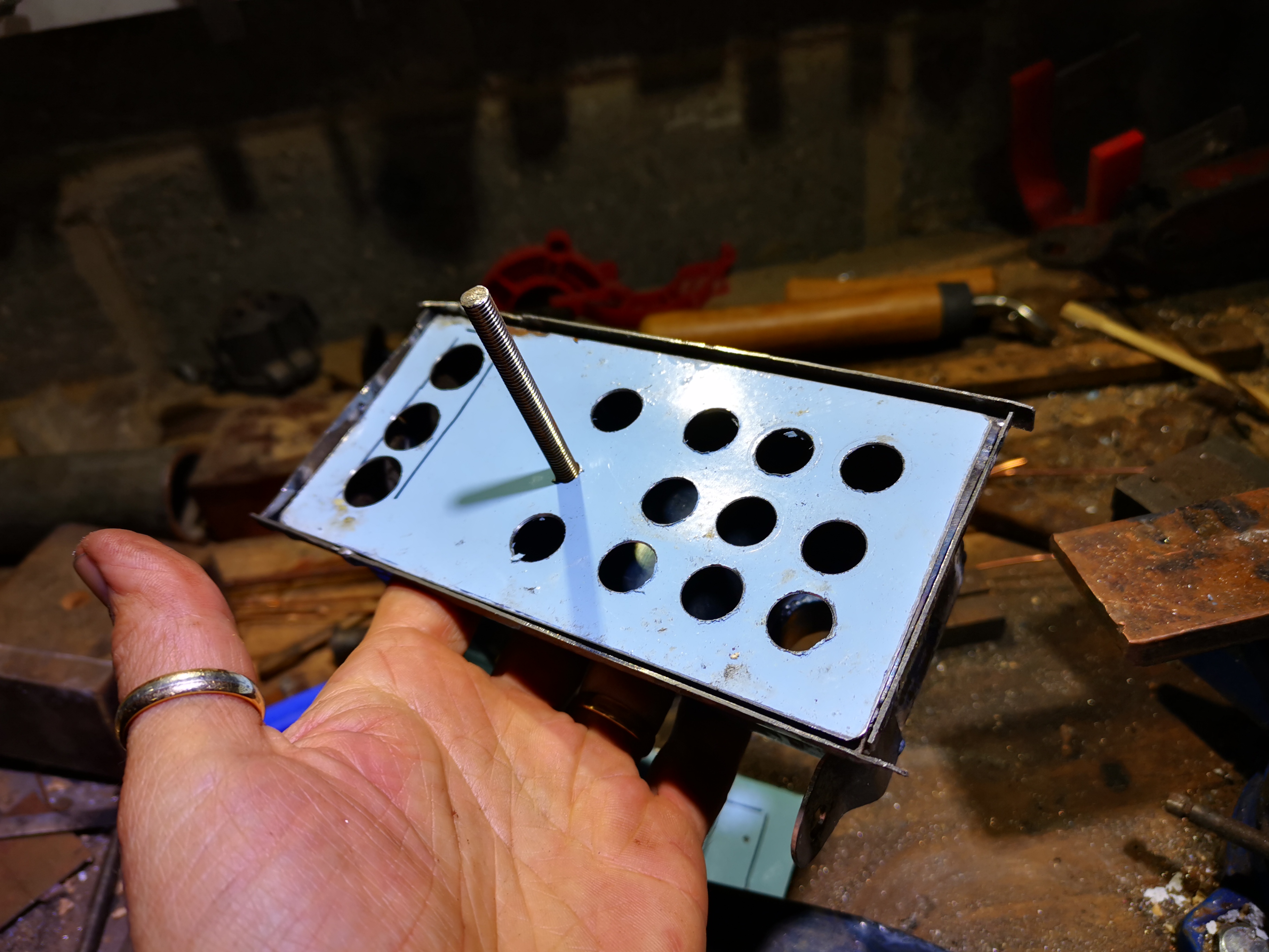
View from the front. That nut is attached to a stud that passes right through the lid, filter element and box and is welded into the back of the box:
Next I spent half an hour tidying up some welds - I used the linisher, some files and a small wheel in the Dremel just to smooth it out before painting. It's not perfect - I'm not spending hundreds of hours ironing out every nick and scratch but we will tidy up the worst of it. So next it's paint, starting as usual with U-POL etch primer.
Here's the completed airbox, coated in U-POL satin matt black. The parts are held together with hot melt adhesive and the element is hand cut from a piece of open cell foam:
Here it is in situ, from the top. I had to change the top bracket since it wasn't sitting square in the frame


No comments:
Post a Comment