This week, yet more QR50 parts, this time the missing magneto cover. I'm hoping that in a week or two there might be some exciting Ariel news, but more on that later if it all comes together.


A short interlude while I travel to Ian Baird's Welding Services shop for some more Argon, followed by welding the brackets in place. I used a plug welding technique for this, carried over from when I used to use MIG for welding car body panels together. You drill a hole in one half, clamp the two parts together and MIG into the hole, creating a little plug that emulates a spot weld. Great! Except it doesn't work with TIG, with a fixed electrode which just burns the outer half away. It's better if you increase the current much higher than you would expect for that thickness, but it steel leaves you chasing a hole with the filler rod. I'll bring the MIG out of retirement I think, or use fillet welds.

With the brackets in place we can finalise the position of the disc. I'm stitching this in place, making sure that it is in right place before I make the weld:

Eight stitches later it is finished:

After a session on the linisher and the wire wheel, I use the usual U-Pol paints (etch primer and satin black) to finish the cover:

And that's it. Before I forget, after stitching the cover in place and trimming it back, I rolled the edge over on a dolly, to tidy it up. I think it looks OK:

For now, the QR50 needs a couple more big parts making, the exhaust and the magneto cover. The magneto cover is available from Honda for about £26, but I like sheet metal work, I have a suitable sheet in stock so let's make one instead.
First job is to measure up the diameter of the magneto housing in the crankcase and calculate the length of the strip we will need to make the cylindrical part of the cover. Then, we can use the bandsaw to cut a strip to length and to a suitable width to clear the rotor nut, with a bit to spare for overlap and errors. Secondly, we need a disc to make the top and a further strip for the gasket face as we shall see later.

The parts can be deburred on the linisher or by hand. The ends of the strips need to be nice and square, so we will use the mitre attachment:

I'll bend the main cylinder around this bit of 4" tube. The finished drum will be about 6" in diameter, but of course the steel will spring back from the 4" cylinder:

I'm using a toolmakers clamp to ensure the starting edge is held tight against the steel tube - I do not want a flat in the cylinder. When it's bent fully round, I test it against the crankcase to ensure it is a snug fit; overlap is trimmed off with a hand shear and deburred. This takes several attempts removing a small amount at a time - we don't want it too short, as that means we will have to start again. When the fit is good, tape the ends close together with a bit of masking tape, before welding as an autogenous butt. You will probably lose the very end of the weld, but that is why we have spare length.

The weld is finished on the linisher and test fitted again. The outside edge is not parallel and is very long, but it's the fit of the inside edge that is important at the moment:

Next job is to raise the edges of the cover. Start with a disc marked with the diameter of the flat part, which is a little less than the diameter of the cylinder. Add maybe 3-4 mm to the radius to fold over as a raised edge:

Over a suitable dolly, raise the edge little by little, working around the edge moving the metal maybe 10° with each rotation:

Try to keep the edge even, and the disc will stay flat; raise it too much at once or move off the line and the face will distort:

Eventually it fits nicely in the cylinder. I put a blob of grease on the rotor nut and assembled the cover to the engine, pushing the disc in as far as it would go but keeping it square to the cylinder:

The grease witnessed that the disc touched the nut. I move the disc back out of the cylinder about 5 mm (for clearance) and marked the inside of the cylinder before cutting it with shears:

Next stop, it's the brackets to hold it in place. These are simply bent up from a bit of sheet - the holes are cut with a cone drill while the bracket is in the flat. There's a similar one for the bottom:

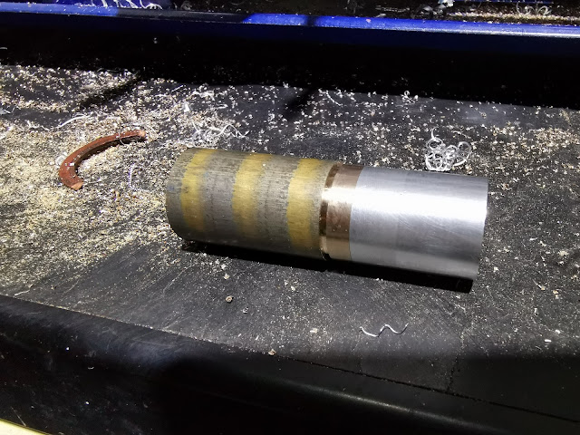
The original Honda version has a seal, which sits in a ledge formed by a second ring inside the main cover. I'll make this with another cylinder:

This too has a raised edge which will eventually carry the O ring:

The O ring is made from a 3mm OD Viton extrusion; I use Loctite 406 for rubbers and plastics. Buy more material than you need and cut it over length with a sharp knife - it took me three attempts to get the fit correct and snug:

Tacking the seal carrier in place. Unfortunately at this point I ran out of gas...

A short interlude while I travel to Ian Baird's Welding Services shop for some more Argon, followed by welding the brackets in place. I used a plug welding technique for this, carried over from when I used to use MIG for welding car body panels together. You drill a hole in one half, clamp the two parts together and MIG into the hole, creating a little plug that emulates a spot weld. Great! Except it doesn't work with TIG, with a fixed electrode which just burns the outer half away. It's better if you increase the current much higher than you would expect for that thickness, but it steel leaves you chasing a hole with the filler rod. I'll bring the MIG out of retirement I think, or use fillet welds.

With the brackets in place we can finalise the position of the disc. I'm stitching this in place, making sure that it is in right place before I make the weld:

Eight stitches later it is finished:

After a session on the linisher and the wire wheel, I use the usual U-Pol paints (etch primer and satin black) to finish the cover:

And that's it. Before I forget, after stitching the cover in place and trimming it back, I rolled the edge over on a dolly, to tidy it up. I think it looks OK: