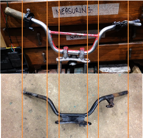
We saw in a previous post how the handlebars that arrived in the QR50 'kit' were very large compared to the original bars - obviously they are normal size bars, but the QR50 bars are designed for small people. The post is here. I made this comparative picture to look at the differences - you can see the relative lengths of the various sections and the substantial difference in the way they are mounted:
What we are going to do is chop them up and reweld them into the proper shape. We start though with the part the grip fits to; the grips, switches and brake lever I have are made for 'pit' bikes and use a smaller diameter bar.
The next step is to chop the brace out:
In the first picture, we can see the rise is too high, so we will chop a bit out of the straight section:
With a suitable prep and a supporting tube, it's easy to weld:
One done, one to go:
That's it, all tacked up; levers next.
Now, here's the thing. The QR has a funky CDI unit that requires a wire to be earthed while starting. This is done with a switch on the rear brake lever, and I don't have that - in fact I don't have any levers. I've bought a pit bike set which includes a conventional clutch lever for the left, and a combined run/stop switch, twist grip and front brake lever for the right, and I have a Honda front brake light switch that I bought from eBay.
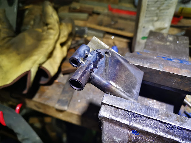
What I'm going to do is build a lever mount for the rear brake lever which will carry the Honda switch to allow the bike to start with the rear brake on. I've made a few bits - there's a tube to carry the switch, made in the lathe; a tube for the brake cable abutment, also made in the lathe, a 'U' shaped section as the lever mount and another 'U' shaped piece to form a spring loaded lever which will hold the rear brake on while you kick the bike over.
Some bench work has these fitting together. You might be thinking, 'why is he making all this stuff?'. Well, QR50s are not exactly common - I think most of them went to Australia; bits are not common and when they do come up, they are hellish expensive - so here we are.
Out with the TIG welder:
And trial fit all the bits:
Next, we have to figure out what angle to cut the mounting such that the lever ends up in the right place when it is fitted to the bars, and such that the brake and electrical cables can be fitted and have a reasonable route:
Tack it in place, and then trial assembly:
There we go, all good:
These pictures were taken two years later, but show you how it ended up:
Here's the rear brake lever in it's final form:


No comments:
Post a Comment