
Well, as I had the lathe set up with the ER25 collet chuck and the fixed steady (for the crankshaft threads) I thought I would prepare the kick start quadrant for the spline repair.
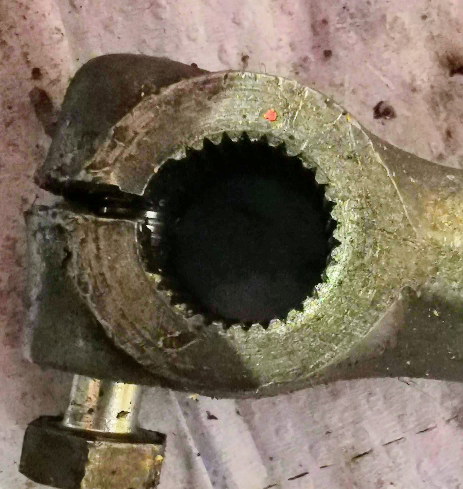
Like a lot of bikes, this has suffered the usual calamity of allowing the kickstart to come loose, fret and eventually turn on the splines. This one looks like there has been some weld repair, and it is full of holes...
I have a Honda Express transmission which I had thought would provide a replacement - unfortunately, it looks like Honda decided this design was inadequate as the Express quadrant is much bigger in this area.
We'll have to fix this one.

First of all I will have to put this in the lathe to clean up the mess

Then, I will have to build up the missing bits with the TIG set, followed by restoration of the splines. Options could be:

I need to look at the short taper behind the spline as well:

With it cleaned up, I can think about welding:

In this first picture, I have laid about 4-5 mm over the end of the shaft, with the machine set at 75 A. This is half a ball, and of course I need to build up a cylinder with a square end. This will probably need some more work:

Laying metal over the diameter:

Laying more material into the diameter, about the tapered section which will need recutting:

This is the kickstart lever. The major diameter of those splines is 13.5 mm and it looks like we have a 30° spline. Inside diameter is about 13.2 mm. It's quite difficult to count the splines, but it appears the full circle would have 30 splines.

Here, I've turned the weld down to a tad under 14 mm, to see where we are:

Here's the length, turned to 18 mm:

We need to build up more in various locations. I've decided to dispense with the peripheral groove, since I don't need it - I can decide where I want the clamp bolt clearance and cut a small slot in the appropriate location later:

Having built it up some more it is time to turn to the final size:

We use the usual dividing gadget to set the lathe up for dividing the 30 serrations:

Here's the tool set up for cutting the serrations:


All cut to the initial stage. Part way through this stage I tightened up the fixed steady which has had the effect of making the later serrations deeper than the initial ones - look at the last ones I cut at about 9 o'clock, against the first ones, about 11 o'clock.

Here's another view. You can see that the serrations are still truncated - the next stage needs to be deeper.

These are 0.05 mm deeper. You can see the form has taken shape by virtue of the small chamfer at the nose of the shaft:

And that is it - or it would be, if mating the two parts had not revealed that the Honda design has 31 serrations, not 30...
It should look like this:

Here we go again:

Like a lot of bikes, this has suffered the usual calamity of allowing the kickstart to come loose, fret and eventually turn on the splines. This one looks like there has been some weld repair, and it is full of holes...
I have a Honda Express transmission which I had thought would provide a replacement - unfortunately, it looks like Honda decided this design was inadequate as the Express quadrant is much bigger in this area.
We'll have to fix this one.

First of all I will have to put this in the lathe to clean up the mess

Then, I will have to build up the missing bits with the TIG set, followed by restoration of the splines. Options could be:
- milling, using an end mill in the lathe and indexing the part in the rotary table
- grinding, using a toolpost grinder
- shaping, using a suitable tool and indexing using the dividing attachment
- machining a plain journal and using a axial pin to provide the anti-rotation feature
I could also make a new shaft to the correct size and make the splines in that, to avoid the building up operation - but then I would have to remove the old shaft and re-weld the new one.
Turning off the damage is pretty straightforward:
Turning off the damage is pretty straightforward:

I need to look at the short taper behind the spline as well:

With it cleaned up, I can think about welding:

In this first picture, I have laid about 4-5 mm over the end of the shaft, with the machine set at 75 A. This is half a ball, and of course I need to build up a cylinder with a square end. This will probably need some more work:

Laying metal over the diameter:

Laying more material into the diameter, about the tapered section which will need recutting:

This is the kickstart lever. The major diameter of those splines is 13.5 mm and it looks like we have a 30° spline. Inside diameter is about 13.2 mm. It's quite difficult to count the splines, but it appears the full circle would have 30 splines.
Here, I've turned the weld down to a tad under 14 mm, to see where we are:

Here's the length, turned to 18 mm:

We need to build up more in various locations. I've decided to dispense with the peripheral groove, since I don't need it - I can decide where I want the clamp bolt clearance and cut a small slot in the appropriate location later:

Having built it up some more it is time to turn to the final size:

We use the usual dividing gadget to set the lathe up for dividing the 30 serrations:

Here's the tool set up for cutting the serrations:

Here's the first few, first stage of cutting. I'm using three passes at 0.075 mm per pass which in theory will give me 0.225 mm height to each serration, which equates to an ID of 13.05 mm. In practice, clearances and flex in the lathe will prove this is not sufficient:

All cut to the initial stage. Part way through this stage I tightened up the fixed steady which has had the effect of making the later serrations deeper than the initial ones - look at the last ones I cut at about 9 o'clock, against the first ones, about 11 o'clock.

Here's another view. You can see that the serrations are still truncated - the next stage needs to be deeper.

These are 0.05 mm deeper. You can see the form has taken shape by virtue of the small chamfer at the nose of the shaft:

And that is it - or it would be, if mating the two parts had not revealed that the Honda design has 31 serrations, not 30...
It should look like this:
Here we go again:

No comments:
Post a Comment