Wednesday, 7 September 2016

W/NG Footrests

The parts book for my 1942 W/NG tells me my footrests should have rubbers.


The part number for the metal bit is 5383-29 but the illustration is not the same as the ribbed footrest Drags sell under this part number, which looks just like the illustration in the 1943 parts book:


I think my footrests should be plain and more round in section than the flat ribbed 'military' one, something like 5393-46 perhaps; thought these are curved unlike either version of 5383-29.

Whatever they should be like, this is not it. The offside footrest has a serrated boss, and fouls the gearbox cover nuts:


The nearside one also has serrations, but is not curved at all - which it needs to be, to get it in the proper position for the brake pedal - at the moment, the pedal is way too close to the footrest.


So I bought two 5383-46 footrests from Drags, and very nice they are too, because if they fitted the singles in 1946 I'm sure they should look the part on my W/NG, and they are made for rubbers.

This is what they look like:


You can see it is a much better fit around the gearbox.

Ignore the socket in the next picture, that is on temporary spacing duty. Someone has cut the taper of the offside (5375-29) footrest mount. Does anyone know how long a 5375-29 footrest mount is supposed to be? My footrest is too far out as shown here.


So in this one you can see that the curved footrest is in a better position for both the brake pedal and the clutch dome:


These are the genuine Ariel 5393-46 footrests on my SQ4, for comparison. This is a 1951 bike, and has a rather different arrangement on the gearchange side to the singles:


On the drive side, see the proximity of the footrest support hole in the primary case to the edge of the clutch dome, and remember that the SQ4 brake lever is different:


The footrests on two different 1949 NH, for comparison. Perhaps not surprisingly these are very similar to the arrangement on my W/NG:


Luckily for me, I have around 8 original footrest rubbers in the pile of parts that make up my Huntmaster kit. Two of these can go on the W/NG. which is early enough to have had footrest rubbers when it came out of the factory. They have also had a dose of black paint:


Monday, 5 September 2016

Missing Speedometer

One of the things that always seems to be missing from my projects is the speedometer. Fortunately I guess all my bikes have chronometric instruments, which do not attract the exorbitant prices of the PA speedos, but nevertheless they are not cheap!

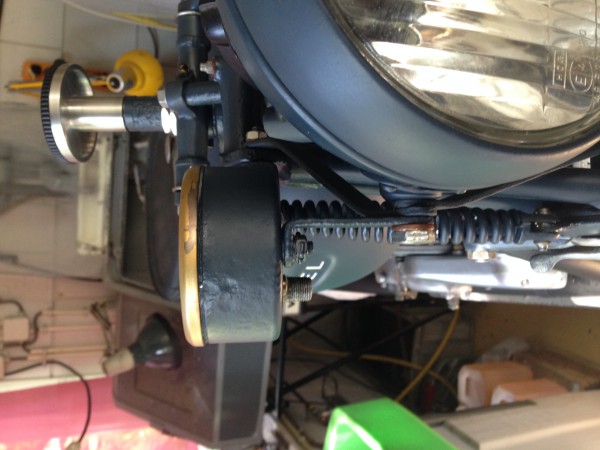
The W/NG was no exception. Fortunately, the drive gearbox is there:


It works, but looks like it is full of crud; the small pinion 5246-38 is missing:


The big one is there though:


The gearboxes are easy to clean out. The two spindles are both retained in place with a pressed plug, a bit like the core plugs you might find in an engine block. The one on the end of the horizontal spindle, that goes into the hub has a grease nipple; the vertical one, that drives the cable is retained by a split pin.

These gearboxes are available in a variety of options:

  1. clockwise in/clockwise out
  2. clockwise in/anticlockwise out
  3. 12:8 ratio
  4. 14:8 ratio

And probably many others. They are quite straightforward to dismantle, though the cast bodies are brittle. Remove the split pin and tap the end of the cable drive spindle with a 1/4" punch - the spindle will push the plug out with it; do the same for the other spindle. clean all the old, hardened grease out and reassemble.


We'll have to buy a cable. It will have a spade type drive:


The small pinion is readily available from our favourite Suffolk spares stockist and is fitted after the gearbox is mounted in the brake plate. I used a split pin, making sure that the legs were trimmed short enough to disappear into the groove around the pinion


Here it is in place. You can see that when it is the proper position, the groove is enclosed in the brake plate and there is little space:


The speedo head is missing of course. I have bought this one from eBay:


It's in very nice, patinated condition and has a light and a trip, unlike the proper S433B military one; but this is more useful to me so would make a sensible choice.

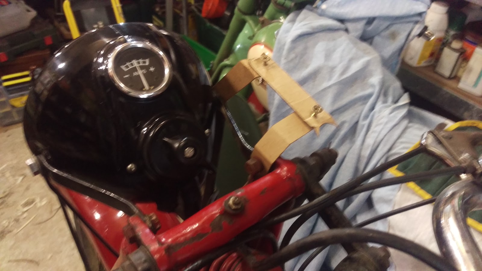
It will need some brackets. 1942 bikes like mine have the separate speedo brackets (5213A-41 and 5213B-41) as shown in the 1943 parts book:


These are the brackets I need:


These are also shown in the 1941 parts book with a different illustration:


So to replicate these brackets, we will make some dummies with 3/4" wide strips of cardboard:


The strip with the two screws mimics the fixing screws on the back of the instrument:


Wondering if I have this rear bracket upside down. I've realised that it doesn't look like the parts book...


The 'upside down' theory seems to be born out by these excellent pictures of 'Burney' a fire-damaged W/NG being resurrected by Vincent van Ginneke of the AOMCC:

You can see that the speedo is at 90 degrees to the front leg of the girder


Top view shows relative position of speedo and headlamp
So let's try again:


Cut a slice of 3 mm thick cold rolled sheet steel, 16.7 mm wide as described by Vincent, not worrying too much about the length at the minute:


Its the bends that matter. Put the piece in the vice and make sure it is perpendicular to the vice jaws:


Two 45 degree bends give us the profile we need:


Clamped in place:


Two holes drilled for clearance on 1/4" bolts:


We will trim up and round the ends when we are finished. No point in doing that until we know it is in something like the right position. Here's my W/NG alongside Vincent's - looking very similar:


So here we have the second bracket, bent up and drilled:


And now, completed brackets waiting for paint.


Compare the W/NG at the museum. Looks like bracket is twisted; mine needs the corners removed!


And another view:


This one looks like it is further from the machine centreline:


Thursday, 1 September 2016

Leak Test

As I may have mentioned I have a leak in the fuel tank. I found a product online called 'Seal-All' which purports to be suitable for leaky tanks and is 'gasoline proof'.

I thought I would devise a little qualification test. These are the bits we will use - ignore the regulator! The plan is to make a hole in one of the tins, seal it, and then subject it to long term immersion in fuel to determine if it leaks, or if the sealant changes.


I made a suitable hole in one of the tins using an 8 mm wad punch, which should be very similar to the hole in my tank which was cut with an over long M8 bolt. The idea is that the area of adhesive exposed to the fuel will be comparable to the real hole in the tank:


I laid the adhesive over the hole and let it cure in this position for 24 hours:


After the cure, it is still soft, like a hard cheese. 

So this is the test setup. I have fuel in the top tin, covered with a polythene bag. This is sealed to the tin with a tight elastic band, but the bag is loose to allow movement of the bag to compensate for volume changes in the air above the fuel, preventing any pressure developing in the can which would change the test conditions; the bottom can is there to catch the drips coming through the sealant from the top can:


We'll leave it for a month and see what happens, investigating periodically so that we can get a reasonable idea of how long it lasts - I don't want to look for the first time at 30 days to find a leak which may have happened after 2 days! For the record, the test started on Wednesday 31st August 2016.

Here is the first inspection, 5 days in:


Still no leaks. The sealant is a little harder - maybe a 24 hour cure is not long enough?

Second inspection, two weeks in; still no leaks:


Its possibly a little harder - I'm starting to consider where this will handle any vibration?

Latest picture. 21st September, three weeks in. No change:


More than four weeks, still no change:


6th October - five weeks:


Still no change on the 12th October - that's six weeks:


October 2024 - this repair still hasn't leaked!