This is a rare item indeed, but courtesy of a few members of the Ariel clubs around the world, I have these pictures. I've been using this modern version:

It's mostly fine, but you have to remove that handle to remove the non-brake side retaining ring since it is recessed in the hub and you cannot get the pins (which are 5/32" diameter, by the way, and about as long) to engage safely in the ring.
The one on the brake side is easy - its not recessed at all. Making a replica of the original will make it easier to get the non-brake side locking ring screwed in, as well as completing the tool kit.
We can see from this next picture that the original locking ring spanner is cast. I'm not going to be able to emulate that - I will be making one on the lathe, welding and using the pillar drill. We can see that the disc is not much thicker than one of the pins - the pin diameter is of course dictated by the holes in the locking ring.
We can see from this picture that the drive pins on the locking ring are very close to the edge of the disc:
We can see a few interesting points from this last picture:

It's mostly fine, but you have to remove that handle to remove the non-brake side retaining ring since it is recessed in the hub and you cannot get the pins (which are 5/32" diameter, by the way, and about as long) to engage safely in the ring.
 |
| Recessed locking ring |
We can see from this next picture that the original locking ring spanner is cast. I'm not going to be able to emulate that - I will be making one on the lathe, welding and using the pillar drill. We can see that the disc is not much thicker than one of the pins - the pin diameter is of course dictated by the holes in the locking ring.
 |
| Part of Scott Williamson's 1949 SQ4 tool kit |
 |
| Part of David Andersen's 1949 VH tool kit |
 |
| Close up of David Andersen's tools |
- the lock ring spanner is about 1.75" in diameter
- the lock ring spanner has a 0.820" hex - 7/16" BSF by scaling from the picture which will match the hub nut tube spanner
So, the plan is to find a suitable bit of hex bar; then use a slice of 1 3/4" round bar or a bit of 3/16" plate (which I have in stock). I've been thinking about how to make this and I've come up with the following sequence, which will probably get modified as I think more about it:
- Cut a rough shape from the 3/16" plate, suitable to fit in the 3 jaw chuck
- Fit the external jaws to the chuck, chuck the plate and face one side with a minimal cut.
- Flip the plate in the chuck and face the other side.
- Centre drill, drill 6 mm, open out to 10 mm and then 13 mm. Bevel the hole slightly.
- With the plate still in the lathe, mark off the PCD of the pin holes.
- Chuck the 0.820" bar and face off.
- Turn a journal to an interference fit for the 13 mm hole and to a length equivalent to the thickness of the plate.
- Bevel side first, push the plate onto the journal using the tailstock to keep it square.
- Saw the 0.820" bar to a suitable length - about 0.5"
- Put the hex in the vice with the flat side of the plate upward
- Weld the plate to the journal
- Put the hex back in the 3 jaw and turn the face flat again, dressing the weld
- Turn the plate to a suitable diameter
- Round the side of the plate with the hex
- Ensure the PCD of the pin holes is still clearly marked.
- Flip the plate in the chuck and face off the hex; bevel the edges.
- Drill the pin holes somehow... ideally indexing in the lathe and using a tailstock drill?
- Use the tailstock chuck to push the pins in square
- Test
- Paint
Step one, saw out the plate:
 |
| Almost there |
Step two, change the jaws of the 3-jaw chuck for the external jaws, and chuck the plate. Then clean up the face with a minimal cut:

Step 4, centre drill the plate:

Next step, drilling the hole 6 mm, then opening out to 10 mm and then 13 mm. I managed to stall the lathe for the first time!


Step 12, facing off shows the porosity nicely...

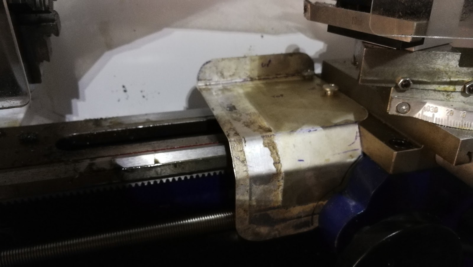
Step 13, turning the plate to a suitable diameter - part way through:

Marking the pin pitch circle diameter:

Ready for drilling:

Some of those voids are actually in the 1/4" plate. Great quality steel...
Dykem applied, ready for marking out:

Before we start machining the holes, we have to set the lathe up for milling. this involves removing the compound slide, bolting down the adapter plate and fixing the vertical milling slide to the adapter plate.

Before we start, we have to make sure the milling vice is perpendicular to the spindle axis. We can do this with a piece of round bar in the chuck, and a small square to set the vice up to the axis.

To drill the six holes at 60 degrees to each other, we need to index the disc. I'm indexing on the hex, welded to the back of the disc - I machine one hole to 5/32" deep, index, then machine the next.

When I've drilled all the holes, I cleaned up the disc with emery. The pins are 4 mm dowel, which provides a slight interference fit on the holes in the disc which are drilled 5/32" (about 3.96 mm) - they are pressed in place in the vice with Loctite 243 (medium strength threadlock - not very appropriate):

The holes in the hub locking rings are flat-bottomed. To provide maximum engagement, I ground the ends of the pins flat:

Next job is to turn the tool to the proper diameter, but first I need to test it:

It's not too bad, but a quick test reveals that I must deburr the pins.
Now finished. The hexagon and the disc have been turned to shape to mimic the cast original, and I have deburred the pins.


Step 4, centre drill the plate:

Next step, drilling the hole 6 mm, then opening out to 10 mm and then 13 mm. I managed to stall the lathe for the first time!

The plate prepared for welding, and the hex cut to length to go in the lathe. The 0.800" hex does not fit through the chuck...

Step 6 done, and the beginning of Step 7: turning a journal for the plate to fit on.

Step 8, the two parts together:

Step 11, welding. Remembering that the only hex bar available is EN1A, it's no surprise that the weld is porous. I'm not sure what the plate is, but that is probably EN1A as well...


Step 13, turning the plate to a suitable diameter - part way through:

Marking the pin pitch circle diameter:

Ready for drilling:

Some of those voids are actually in the 1/4" plate. Great quality steel...
Dykem applied, ready for marking out:

Before we start machining the holes, we have to set the lathe up for milling. this involves removing the compound slide, bolting down the adapter plate and fixing the vertical milling slide to the adapter plate.

Before we start, we have to make sure the milling vice is perpendicular to the spindle axis. We can do this with a piece of round bar in the chuck, and a small square to set the vice up to the axis.

To drill the six holes at 60 degrees to each other, we need to index the disc. I'm indexing on the hex, welded to the back of the disc - I machine one hole to 5/32" deep, index, then machine the next.

When I've drilled all the holes, I cleaned up the disc with emery. The pins are 4 mm dowel, which provides a slight interference fit on the holes in the disc which are drilled 5/32" (about 3.96 mm) - they are pressed in place in the vice with Loctite 243 (medium strength threadlock - not very appropriate):

The holes in the hub locking rings are flat-bottomed. To provide maximum engagement, I ground the ends of the pins flat:

Next job is to turn the tool to the proper diameter, but first I need to test it:

It's not too bad, but a quick test reveals that I must deburr the pins.
Now finished. The hexagon and the disc have been turned to shape to mimic the cast original, and I have deburred the pins.