Wednesday, 10 June 2020

QR50 - Handlebar survey

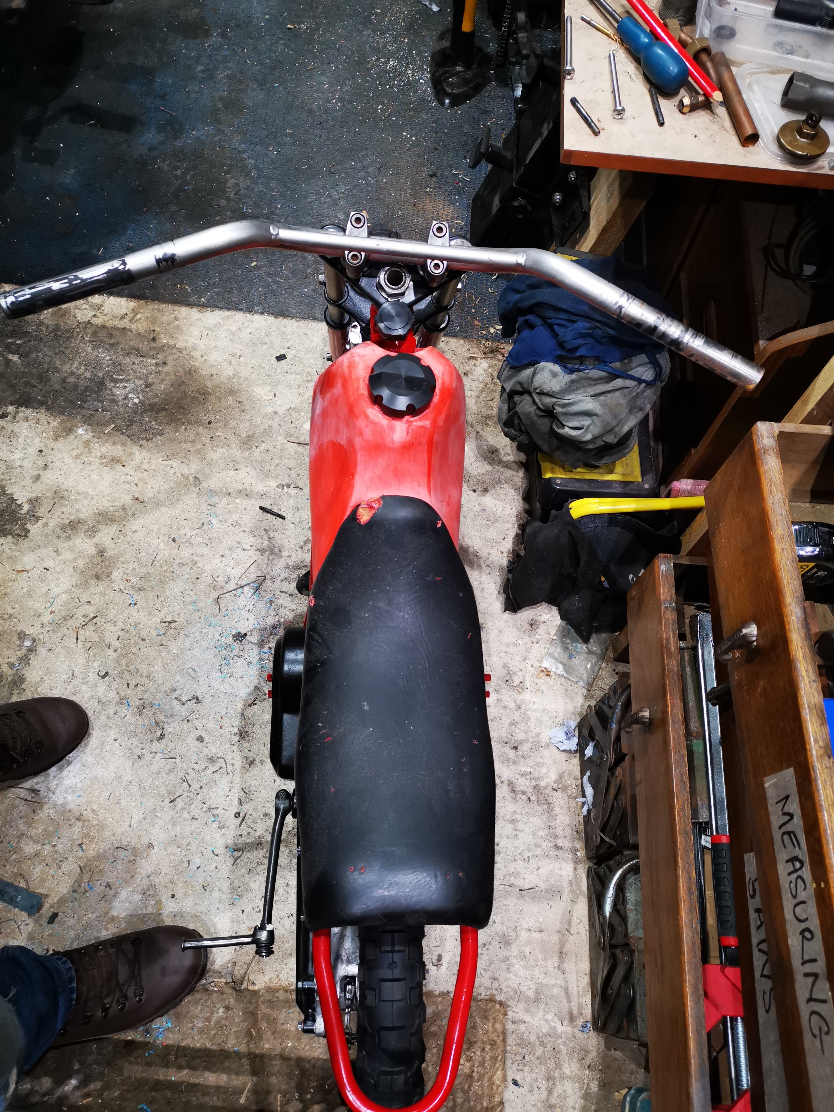
Regular readers will know that the kit of parts did not include an original set of handlebars, which throws up a couple of problems relating to the rear brake lever and the size of the bars themselves. We'll talk about the rear brake lever another time, but if you take a look at these pictures you will see that the bars are much higher and wider than the original equipment:


We can see from the picture below that the original equipment bars rise maybe half the distance from the top yoke to the bottom yoke. On my bike, you can see this rise is almost as much as the full yoke to yoke distance. Reducing this height would mean losing the brace.


The additional width is simply outrageous:


The original bars are actually welded to a sheet metal cradle that bolts to the top yoke - they don't use the clamps my bike has. In these two pictures, you can also see that the ends of the bars are more or less the same length as the seat width - mine are much longer.


The bends above the top yoke are inboard of the stanchions on the original bike, so the centre section between the clamps would have to be reduced. This would mean losing the clamps.


So, there's quite a lot of work to do to get these anywhere near original.

Tuesday, 9 June 2020

QR50 - assembling the forks

We are approaching assembly time on the QR50 build now, and it will be nice to get it off the bench and to get back onto the Huntmaster. It's been fun and it will be a smart little bike from which I have learned a lot, but I have too many projects at the moment and I want to see the Grandchildren riding this one.

So, while I wait for the gasket set, and for some time to start on the tinware let's assemble the front end. I've used the hone I made to clean the paint out of the yokes, and I use an M8 bolt and a bit of sheet metal to open the clamps a bit, so I can slide the new stanchions in. This is simple, though the balance on the bench is now a bit front-heavy. I hang a big weight on the back.


Looking at my handiwork I notice that the top yoke hits the oil filler - so that was why it was dented on both sides. If you look at this picture, you will see the reason - the steering stop is bent out of the way:


That's easily fixed with an adjustable spanner.


Next, I can assemble the front brake and put the wheel on. It looks great.


Sunday, 7 June 2020

W/NG - Smoke and tappets

Having recently retired around the time that the sun came out and the Coronavirus lockdown regulations were loosened here in the UK, the bikes have been seeing a bit of use. This week, I went out with my son on a ride around Coltishall, Norfolk:


That's his Interceptor, which is a fine machine with power low down, a nice seat height and good balance. We tootle around for a bit, testing out the W/NG's new baffles which seem to be cutting the noise down but also seem to have affected the idle - it now dies more readily than it used to.

However, I adjusted quite a lot of play out of the tappets before I left and that reduced the clatter quite a lot, and the bike seems to be going well. I had it up to 60 on the way home, though by the time I stopped there was smoke pouring off the cylinder head and there was quite a lot of oil about - disappointing, as I had resealed the rocker shaft unions which had been weeping for a while. I resealed them discarding the traditional fibre washers for soft aluminium washers, so we will see how that pans out.

So, back in the workshop the spanners are out to have another go at those unions. There's oil everywhere - under the tank, on the mudguard and down tube, all over the timing cover. It has never been this bad.

Then the penny drops - Numpty Spannerman has been at it again, taking stuff to bits and not putting it back correctly. The front rocker cap has gone.


I've often found that I've subconsciously registered some change in engine note or handling performance during a trip, only to realise the cause much later - the senses are very good at picking up small changes. This time, on the way down I had noticed a deepening of the engine note and on arrival there was more oil about in new locations - differently shaped dribbles even.

So that spelled the end for the old brass rocker caps, one lying in a gutter somewhere in Norfolk and the other consigned to the spares box, to be replaced by these fine reproduction examples from the AOMCC Singles Spares scheme. Also shown here are the clips that hold them in place - this is a W/NG only part, and provides some deterrent for the caps to loosen off completely.


Whilst I had the tank off, I took the opportunity to check the tappets again, look at the decompressor seals and check the timing. The tappets and timing were spot on but while I was removing the rocker box bolts to fit the new clips I returned the clutch cable to it's proper route - it's not supposed to go through the tank mount like this:


Here's the decompressor, removed and dismantled:


I've fitted a Dowty washer between the body and the rocker box to seal that joint. Third from the left is the rubber washer, which is rock hard - I fitted a small O ring behind this. O rings are not for use in dynamic sealing applications, but the decompressor rarely moves so I think it will be OK. I've had a quick look for an oil seal that will fit in here but that seal is maybe 2 mm thick - way too thin for an oil seal. Perhaps I will turn a simple carrier to fit a couple of O rings or change the decompressor body to allow an oil seal to fit.


I'd not noticed this weld repair before.

So that was a useful couple of hours work - I had a look at the clutch adjustment as well. These old bikes are so easy to work on.


TS125 - A new bike joins the flock

The trusty L200 earns it's keep again today, first transporting an ancient wooden door to the cottage to be adapted for the kitchen, and secondly to collect my son's latest acquisition, another TS125 - his fourth MZ:


It's in decent nick - the seat and battery cover are missing, but the carburetter is there and the barrel and piston are in good shape:


He has a registration plate for it which shows it is on the DVLA computer and has lain untaxed since 1994.

Saturday, 6 June 2020

QR50 - Sorting the centre stand

Lots of my bikes, from the Bantam to the SQ4, the W/NG, FH and now the QR50 have problems with stands, usually because they are worn out on the feet or that the mounting is damaged in some way. The QR is an exception, sort of, in that it has a worn mount (which we fixed earlier) but it's also the wrong stand. I believe it was meant for an NC50 Express.

If you take a look at this picture you can see that the bike is teetering on the stand - the slightest shove forwards will have it off:


Here you can see why - the shape of the stand does not allow it to come forward far enough for the spring to go fully over-centre and hold it down:


If I push the stand against the stop, the spring shows the problem a different way - with the stand in this shape, the spring is too long:


We'll reshape the stand. Using a hacksaw and a Dremel cut off disc, we will cut the stand and bend it to alter the position of the feet when the stand is down. This also alters the position of the spring monting, extending it:


The stand feet are much further forward and the bike is more stable:


Since the stand spring lug is now further away from the engine end of the spring, the spring is tight and the stand is held firmly up:


A bit of TIG and all is set in stone:


Wednesday, 3 June 2020

QR50 - Wheels

In common with a lot of this bike, the wheels were a right old state. Not only were they covered in the ubiquitous red paint:


... but the tyres were rock hard and both had to be cut off. Not that unusual for an old machine and I have indeed cut a few tyres off in my time:


What I hadn't seen before was this - it is a 14" tube folded up in a space where a 10" tube should be:


Stripping the wheels involved the usual hours with the wire wheels, followed by some U-Pol etch primer. The brake drums are masked off:


And then some U-Pol wheel silver:


And a couple of new tyres and tubes from eBay:


A brief period of struggling ensued, during which there was loud swearing and quiet persuasion according to the stage of the process we had reached, and then it was done:


Tuesday, 2 June 2020

QR50 - Assembling the Transmission

Now that we have the engine back together, we can look at the transmission.

The QR50 has an automatic (centrifugal) clutch, with a chain drive to a reduction gear set up at the rear wheel - it is single speed, and the transmission acts as a single sided swinging arm. The wheel is mounted on a single sided axle, running in a sealed ball bearing in the inner case (that forms half of the crankcase) and a plain bearing in the outer cover. We can see it fitted to the bare case here: 


First we need to set up the drive chain tensioner and rubbing strips. It's a good idea to use some Loctite 243 in here to ensure we don't have a bolt come loose:


Here's the complete assembly:


I've mounted the clutch drum. This has the engine sprocket welded behind it - I have fitted the drive chain and the intermediate sprocket, which drives the rear axle. the chain is pretty loose and I think we may need a new one


Here's a close up of the tensioner. As you can see there is not much travel left - the upper path is the slack side of the chain as this engine runs backwards, by which I mean it rotates in the opposite direction to the wheels.


Here's the crankshaft taper and it's woodruff key:


Here's the clutch and final drive pinion in position. You can see the two pawls which are driven by the kickstart:


The case needs etch primer and a lick of satin matt black:


These are both U-Pol paints


Here's the kickstart quadrant and it's spring in position in the outer case:


The outer case has a couple of neat features. You see that cast slot linking the interior to the screw hole - that's the drain. there is another similar arrangement for the level plug:


Here's the drain plug from the outside:


Outer cover fully assembled with Threebond 1215 used for sealing. Unfortunately, it appears that the kickstart relies upon a fibre gasket for the proper axial clearance - the kickstart does not return with the case screws tight. It all has to come apart again to have the OEM gasket fitted, which does the trick. I fitted it with 1215 one side and grease the other, so it will come off easily next time - and maybe preserve the gasket for re-use.


This is the brake cable bracket:


I've fitted the rear wheel and centre stand to have a look-see; I've also assembled the rear brake.


I can see now that the centre stand is misshapen - possibly bent, or the wrong stand. It needs to come forward 10 - 15° or so which will stabilise the bike and allow the spring to work to retain the stand in the up position. I think I will also straighten that kickstart...

Monday, 1 June 2020

Retirement Day 1

 After 27 years, my oil industry career has come to an end; indeed, my employment as an engineer has ended after 34 years though of course, you can take the engineer out of his employment but you can't take him out of the man.

My first job is to take a ride out on the W/NG to meet my son for a bike ride.