Friday, 26 July 2013

Coupling Gears

Things are moving on... Not much progress lately, because despite the fact that I am not at work at the moment there is a house to be refurbished and summer weather to be enjoyed! Plus, I have a little Off-Grid Garage project to tell you about later.


So, bottom end is in and now we can fit the coupling gears. Easier to do on the bike, since we will be heaving the cranks about and we don't want the engine moving about.


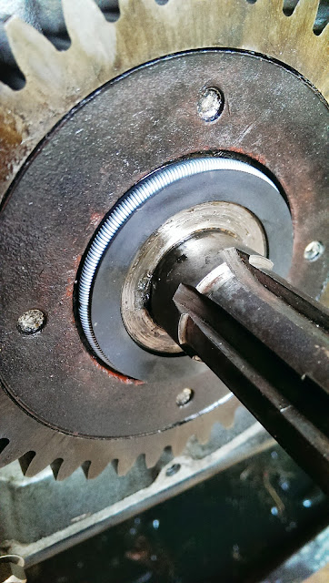
Here is the coupling gear 'pusher' tool, supplied by Drags, and an essential piece of kit. It has two large adapter nuts each with two threads - one for the pusher rod, and one for the crankshaft. You'll note that the threads on the cranks are different, hence the need for two adapter nuts. At this point, you will have the Woodruff key in place, and the coupling gear keyway aligned with the key. You won't be able to see it in a moment!


The pusher tool is actually a puller, since it pulls the crankshaft into the coupling gear. You need the coupling gear puller to go with it. The puller is assembled onto the gear - and now you don't know where the keyway has gone... Grease that pusher rod thread (to avoid it galling) and start turning - you will need a significant torque and you will have to lock the crankshaft using a bar through one of the rod small end eyes. Use two timbers to prevent damage to the crankcase mouths. Oh and a word of warning - do not swing the crankshafts about without the coupling gears fitted. The rods WILL hit each other and you don't want any nasty dings.


You need to make sure the coupling gears are properly aligned. The gears will only go onto the crankshafts one way, and there are dot marks to align the front and rear cranks properly. Align the gears so that the tooth marked with one dot meshes between the two dot marks on the other gear.

Whilst the coupling gears are identical, one of them will be marked 'F' for 'Front'. Fit this one at the front, and you will maintain the wear pattern established when the engine was last running.


When you are done, fit a new oil seal to the rear crank and do up the nut on the front crank.


Next, trial fit the coupling gear cover. No bearing in this one yet, but those studs are in two different lengths. The long ones pass through the dowels at 3 o'clock and 9 o'clock.


Then the primary case inner:


Then the outer, tensioning the sidestand spring


Then you find the clutch cover screw holes are stripped, and that's why we do trial fits!


Then the battery carrier. The shiny fibreglass battery is going to need some matt black paint and a spray of oil or WD40:

Looking good isn't it!

Back in the bike

And so, bottom end set up, we can put it back in the bike.

No pics I'm afraid - just this one. That's me trying to figure out why the last engine bolt won't go in.

Hot tip - fit the rear ones before you fit any of the front ones! and make sure the oil pipes are hooked up to their stud before you fit the engine bolts!

End Float

So now we have the crankshafts, rods and cases assembled:

Ain't she pretty?

Next stop, setting end float. Not a difficult job, but you'll need a supply of shims and the right kit to measure the end float.

The Square Four is designed such that the timing side bushes form the datum against which the end float is measured. Many current machines are also built such that the timing side bush is responsible for taking any end load (there shouldn't be much) from the crankshafts into the cases, since most folk fit main roller bearings without the original lip.

The load is taken into the bronze face shown here. This is the rear crankshaft:


The front one is similar:


Excuse the picture quality. Blackberry camera - 'nuff said.

There is a large, thick washer fitted of the end of the crank to take the thrust into the bush:


The shims shown in this picture fit between the large washer and the end of the crankshaft, and hence the gap between the crankshaft and the face of the timing side bush. This is the 'end float' and should be in the limits 0.002" - 0.004". Draganfly stock the shims.

This is how you set up to measure it:


Here, the dial test indicator is set up on a magnetic base fixed to one of the engine plates, which I have temporarily fitted to the crankcase for the purpose. You can move the crankshaft by hand, to & fro, and the DTI will show you how much it moved. You add shims until you have the movement to spec. If it doesn't move... you probably have the bush nipped up between the crank and the washer. Add all your shims! Take them away until you have the right clearance.

Preparing the Crankcases


This, as all you classic motorcycle fans will know, is a sump plate. It is extremely nasty - it is pitted, bent, and is about as flat as the surface of the moon.

I'm afraid it has to go in the bin, to be replaced by one of Drag's excellent new ones complete with drain plug and magnet. Theirs are flat, thicker and made of nice strong modern aluminium!
 
Here it is in place, trial fitted with the pick up pipe and the suction strainer. To the right of the timing side main bearing, you can see the riveted cover over the drain from the oil pressure relief valve.

 
You can also see in that picture that the oil pick up pipe bolt has been wire locked into place.
 
And unfortunately, that is where the picture record ends. My camera packed up, and now I have no record of actually assembling the cranks into the cases...
 

Until we get to here, which is just to record that I did close up those tab washers correctly! That's plumbers pipe cladding protecting the rods, by the way.


Crankshaft Assembly

Clean those oil ways. If you recall, we dug out the gunge during strip down. During the rebuild, we used various sizes of bottle brush to get into each oil way and scrub them clean. You will be able to see the ends of these brushes by looking into the appropriate oilway.


Before you attempt to clean the oil ways in the crankshaft, make sure you understand the lubrication system. Mr. Waller, as you would hope, has a good illustration in his book:
4G Lubrication System

The picture he shows is from the iron-engine 4G, but it is similar for the Mk1 & Mk2, with the following exceptions:
  • the Mk2 uses a gear pump, not the piston pump shown
  • the Mk1 & Mk2 take their rocker feed from near the rear crankshaft, from the pump return to the tank
  • the oil pressure relief valve in the Mk1 & Mk2 is in the end of the front crank. There is a drilling from the outboard side of the timing side bush into the crankcase, protected by a small sheet metal cover (shown here) on the inside which is riveted to the crankcase.
You can identify each of these oil ways in the crankshafts as a separate drilling, and clean them individually. Note that the long drilling between the crankpins, the one that passes through the central flywheel, is drilled from both ends and is not straight in practice.

Use some new plugs for the oil galleries. Punch and Loctite them in place.


Next stop, connecting rods. As you will have recorded, when you stripped the engine, the 'O' mark on each rod faces the front. We are using new nuts, torqued to Ariel's specification and provided by AOMCC hero Brenton Roy.


Go and have a beer. When you have finished both crankshafts, you will have earned it!


Oil Filter

These are a few shots for the record of how the oil filter ended up after moving the pipe around and bending up the copper return pipe:
 
Filter mounted as high as possible, angled so the element can be easily removed

From underneath. You can see how the element comes out easily

The hoses curve around the gearbox. You can see the special copper return pipe with a 150 degree bend

'58 Huntmaster

Well it looks like the itchy Mouse Finger has been twitching again... This was, like the Bantam, another eBay accident and what I thought was a low bid - "I'd like it at that price but I will never win it" - turned out to be the best price on the day.

This is the original eBay text:

1958 Ariel FH Huntmaster 650cc basket case
Here is a good opportunity to acquire a very worthwhile project for next winter!
This Ariel Huntmaster is generally complete and in sound condition.
The engine is not the original but appears complete and in good condition. The original crankcases are also included and could of course be built into the engine to make the numbers all matching. Gearbox is complete and in one piece all looks good. Wheels are also complete, rims obviously poor condition.
Exhaust down pipes are as new, one silencer is missing.
Smiths 120mph chronometric speedo is there & looks good.
The bike  has its original buff log book registration 39 FRB. I have corresponded with DVLA and they inform me that they have a record for the bike on their computer and a V5C can be issued subject to an inspection at local office.
The old buff log book shows date of registration as 6th January 1958, the bike was supplied by David Tye Ltd, Cromford, Derbys.
The bike looks to have only had two owners.
Frame number is CAPR 10669, engine number CNLF 4656
This would be a very good project , and now is the time to buy it so that some of the prep work can be done over the summer and everything got together for rebuilding over the winter.
Don’t miss this opportunity to restore a very dependable old Ariel to its former glory!
Selling for Spares or Repairs as seen in the photographs.
Please note everything in the photographs is included in sale and there are no extra parts not in the photographs!

And as the man says, it is virtually complete. The horn is missing, and whilst the engine bolts are there, there are very few fasteners. All the tinware is in pretty good shape, though the seat base will need some welding; there are two small dings in the fuel tank; the gear lever is missing; the switches, lights and speedo are all there; the K2F magneto & dynamo are there though the pickups are missing; the forks are straight and clean; and lastly all the numbers match up.

Here are the pictures:


Eventually it will look like this:


Not sure who's bike this is, but it has twin exhausts - mine currently has a two-into-one


It has the same tan seat, and it has the airbox (though the hose is missing):


I had to buy mine on eBay, at vast expense. At least it is an original one:


My gear lever was missing too.

This lovely machine has a FERC, which mine doesn't:


That's the Fully Enclosed Rear Chaincase, to the uninitiated...

Saturday, 20 July 2013

Phase 2 - and wheels...

Regular readers will know that I didn't plan to start any finishing work until I had completed mechanical assembly, such that I could give myself some time for research and so that I wouldn't end up drilling holes or cutting & welding components that were already painted. This is a great philosophy when you are making modifications or when the bike is so incomplete that you are forced to buy parts from more or less reliable sources.
 
A case in point is my indicator brackets:
These have moved all over the place on the 'L' stays in an attempt to get them in the right place.

However, a mechanical build followed by a final build after painting doesn't work with the wheel rims and their gold lined Damask Red centres. I didn't want to have to break these down again for painting, since I will be trimming the spokes to fit. Wheel building is also time consuming and the wheels probably won't be modified at all.
 
I collected the rims from JD Wyatt in Thetford a few days ago, so I am all ready for wheel building now. When discussing the wheel plating with Tony at JD Wyatt, he advised that with a painted centre it would be wise to avoid polishing the painted area and leave it in the as-blasted finish, so that is what we did:
 
 
So, now we need a painter. Of course, I want to have the wheel rim centres matching the tank, so I'll have to get that done at the same time. This is starting to look expensive...
 
Aerographics of Horsford, near Norwich are a long established company set up by John Spurgeon back in the '80's specialising in custom paintwork for trucks, cars, bikes, scooters - you name it, they have done it. They are set up in old farm buildings in an area once renowned for apple farming, and have some great work shown in their website.
 
I spent an hour or so with John learning about his company. John has a wealth of experience and has painted several Ariel tanks before. We looked at many images of Ariel tanks while discussing the location of the lines. This is quite involved, since Ariel hand lined their tanks (so no two are necessarily identical) and many restorers have 'done their own thing' over the years. Additionally, some of the source material shows dimensions for the lines that would leave them visually too close to the badges or the knee grips.
 
So, I took the whole tank to John with badges and the knee grips intact and we laid out the lines in masking tape:

 
So there it is. John says he will turn this and the rims around in 10 days, so watch this space...