Wednesday, 4 December 2024

FH - finishing the clutch

 Grabbing a few moments in the workshop, sorting out some knobs for the wardrobe I was able to give the FH a little bit of time clearing up the deck of the hydraulic lift and terminating the clutch cable. 

Over the years I've accumulated a collection of nipples and ferrules for cables along with a couple of adjusters and other bits and pieces which I keep in this little box.


The first job when terminating the clutch cable is to fix the pear nipple to the gearbox end, clamping the bare cable in the die and mushrooming the end, with the nipple in place of course.


You pull the nipple down to the mushroom the end of the cable holding it in the vise nipple down. Then you can use a large soldering iron to heat the nipple, dunk it in flux and apply some solder. Don't be tempted to use a gas torch because you will overheat the cable and ruin the temper. Probably the first time you will find out about this is when the cable breaks at a traffic light or while you're sitting behind a car.


If you are sparing with the solder you can make a nice little job without any extra work. You might need to run a file over the end of the nipple in case you've been a bit enthusiastic with the solder.


Hopefully you haven't got any solder on the shank of the nipple, stopping it fitting in the clutch lever.


I terminated the lever end at the handlebar with a brass nipple because I didn't want to use the diecast zinc nipple that was supplied with the cable. I have no idea whether the cable was properly terminated inside that nipple or not - perhaps I should cut it apart and have a look. 

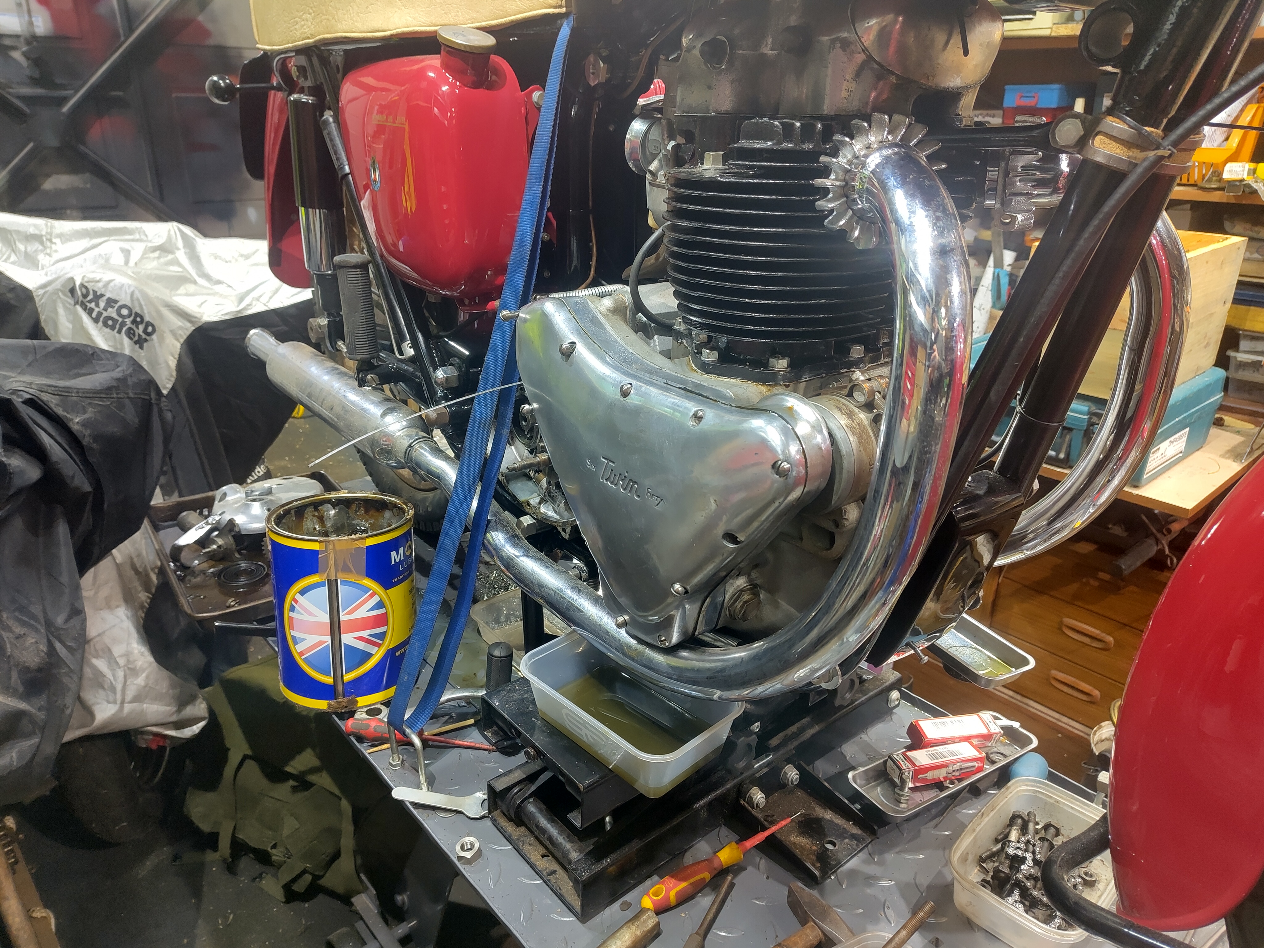
Here's the bike as it stands today - I'm going to have to buy a new clutch dome or at least replate the original one shown here. For some reason the screws won't tighten down on the dome - it appears that they are a fraction too long or are expecting to use shake proof washers.


Monday, 2 December 2024

FH - little bits

 A short visit to the workshop today got a few little bits done. I've removed the oil tank and fitted a bolt into the seat base above it, and I've tightened up all the seat bolts now so that is secure. Unfortunately in putting the oil tank back I cannot refit all the earth cables - I will have to remove the toolbox again to be able to get to the bolts. I do however have to order the voltage regulator to rebuild the RB108, so that will entail removing the toolbox.


Tidying up the bench I did manage to find the inspection cap for the gearbox so I have given that a bit of a polish on the wheel and refitted it.


I've terminated the HT cables and fitted the plugs so they are ready for first start - so that's oil, sparks, compression and a kickstart. All I have to do now is bolt the carburettor in place properly with some gasket sealant and I will be able to connect up a temporary fuel supply and give it a kick. 

This next bit is the rubber cable tie for the front brake. It doesn't fit properly because my mudguard with its repairs is thicker than was originally intended so what I've done is to increase the width of the groove in this rubber piece, so it should now fit.


The last bit today is just to record that the frame clip behind the oil tank has a new half inch long bolt specially made to complete the fitting of the oil tank.

Sunday, 1 December 2024

FH - rear brake linkage

 Another little bit of progress today, the brake linkage has been reassembled after a bit of a struggle. It's good to know that you can actually get the lever and the linkage hooked up without taking the footrest off, and that without taking the exhaust off. 

It's quite apparent however that there is an awful lot of friction in the system. It has to be said that I have not lubricated either the cable or the brake lever, but the bell crank has been greased. The other point to mention here is that at some point in the not too distant future, these parts will all need to be plated.

 We'll see how we go over the next few days.


FH - where are we again?

Doesn't she look great?


  A few weeks after the last catching up post I'll write another one. It might be a bit boring for some but it's very useful to have a list of where you are and what you've got left to do, especially as there are some tiny things that get forgotten very easily - for example I've put the new gearbox inspection plug on the rocker box, and now I can't find the rocker box inspection plug...

I’ll summarise where I am in order to work out what to do next:

  1. Engine: the engine is basically finished. Ignition timing is done, the oil lines are connected up and I have done the circulation on the power drill and proved that the lubrication system works properly. The next step is to finish the head steadies for which unfortunately I have to lift the rocker box slightly in order to get the nuts on. Thinking about this again, I just fitted the drive side exhaust and I'm well on the way to fitting the timing side exhaust and both of these interrupt access to the head steadies...
  2. Oil System: the lubrication system is working as I said but I've realised the oil tank will have to come out because one of the seat bolts is missing; and actually the oil tank isn't bolted in properly. There's also a small leak coming from the return filter.
  3. Fuel system: carburettor needs gasket sealant and the air cable shortening.
  4. Ignition system: HT leads need to be terminated into their caps, and the plugs need to be screwed in.
  5. Gearbox: so today I have put the kickstart case back on as you will have seen in a previous post, but I seem to have lost the inspection cap. I need to fit the gear position indicator, fill the gearbox with oil and solder a nipple onto the clutch cable but then we'll be done.
  6. Clutch: I'm fairly confident that the clutch is completely finished, apart from fitting the dome.
  7. Chains: primary is in, tensioned but not oiled; secondary has a dummy fitted.
  8. Exhausts: the timing side is fitted but the drive side is still loose. Both of the finned clamps need to have screws made up on the lathe.
  9. Electrics: the electrical system is more or less working with a couple of exceptions. The instrument panel is waiting for the speedo to come back from Chronometrics, the battery is still wired negative earth while the dynamo has not been flashed to suit. The voltage regulator enclosure still contains the original RB108 components which will need a modern conversion to suit the VRLA batteries.
  10. Control Cables: the throttle and front brake cables are finished; the air cable needs the nipple moving about half an inch and the clutch cable needs both nipples replacing and the inner cut to suit.
  11. Wheels & tyres: these are parked until the machine is running. I might have a look at the front brake shortly, just to clear it out before I am tempted to ride the bike around the yard!
That about sums it up. Cables next?

FH - replacing the kickstart cover

 We are inching ever closer to starting the engine now; the timing case screws have all been cleaned out (and shuffled around in some cases - the 'medium' and 'long' screws are only 1/8" different and a couple were mixed up) so we need to get the gearbox together.

For the record, the rather mangled mainshaft tab washer is bent up against the flats and the 5/16" ball is fitted with the correct pushrod and mushroom, lubricated with Morris K400EP:

The kickstart cover components are assembled, though in this shot the spring is not tensioned:


Here we have the levers fitted, spring tensioned and the levers wired together:


The next step was to turn the cover over and apply some Wellseal to the gasket face. I stuck the gasket to the Wellseal, and applied some more to the gasket. Because I'm using oil in the gearbox, I'm going to ensure that there is some grease around the main leak path which is the speedo drive in the bottom of the kickstart case. I've applied some Morris K400EP to that area slapping it in all around the gears before fitting the outer kickstart case. 

There's no pictures because this is a bit of a two-handed activity but suffice to say the gearbox cover went on very easily - much more easily than is typical with a BA or CP gearbox. In this next picture it's all screwed down with the new Acme stainless steel screws. 


It's looking great and I'm very pleased, though I'm a little bit concerned that the kickstart spring needs another turn.


Friday, 29 November 2024

FH - pillion footrest

This post is to show you how the most simple small problem takes up and inordinate amount of time. You will remember that I mentioned that one of the pillion footrests was damaged and that the screw wouldn't go in. Here's the footrest mounting I'm talking about:

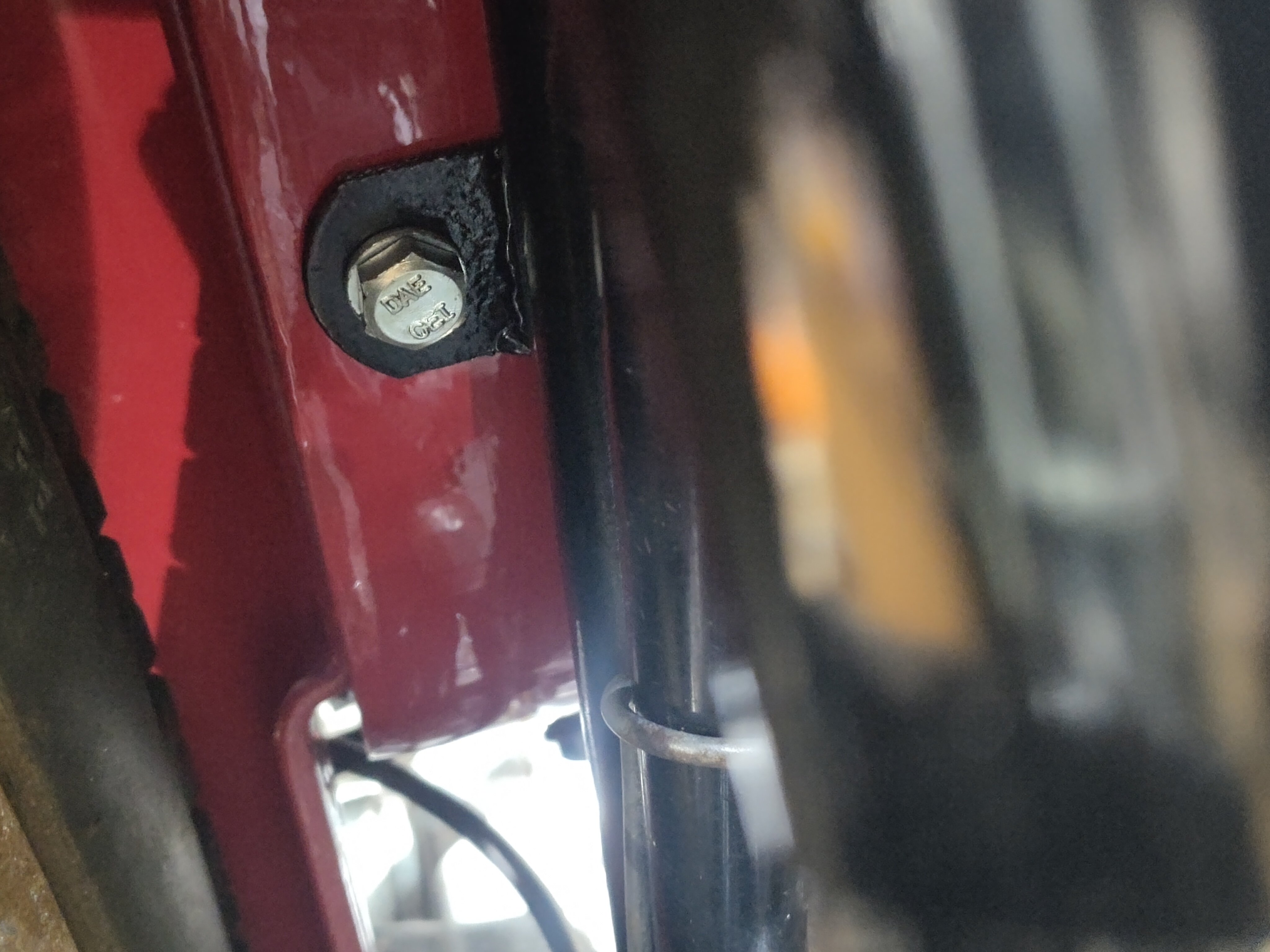
There is or appears to be a burr on the left hand side of the hole. Actually the whole footrest mount has suffered an impact from the left and the hole is distorted. I spent some time with the Dremel and a small grinding bit removing the burr and relieving the hole on both sides. The screw still wouldn't go in and I resolved to take a slightly different approach:

The new approach was to take the screw and stick it in a collet in the lathe and relieve the diameter of the head by a small amount, leaving the original diameter on a millimetre or so of length so that the outward appearance wouldn't change. This allowed the screw to go into the distorted hole, retain the footrest, and for none to be the wiser.


FH - HT leads and plugs

 The FH is going to be fitted with a pair of Champion L82C plugs as an equivalent to the Lodge HN originally fitted. The rubber plug caps came with the refurbished magneto.

The HT leads, copper cored rubber, are the same length on both pickups. As I haven't consciously timed the magneto to a particular cylinder, they may be the wrong way round.

We will leave cutting them to length until we have it running.


Thursday, 28 November 2024

FH - engine finished

 Yesterday I spent a bit more time attempting to finish the tappet covers. After clearing the threads in both the covers, clearing out the locating pin holes and straightening one of the locating pins on the inlet I finally got them to fit. The part numbers are identical for both inlet and outlet covers, but for some reason the one I had on the inlet fits the outlet and the one I had on the outlet fits the inlet. Go figure. There's obviously something around the locating pins, and I did notice that the original centre screw is longer than the one that I made; however, they are both on and done up and finished. 

Next I moved on to the timing cover with Wellseal and grease either side of the gasket as this cover comes off fairly regularly. 

The dynamo chain area is now liberally coated with semi-fluid grease and the cover is on. Some of the screw holes are obviously not clear for their full length and now that I have new Acme stainless steel screws I will need to run a tap through some of those holes again. I've ordered a tap from Tracy Tools - they do a very long (and expensive) tap called a 'nut tap' which will do the job nicely. 

The 'nut tap' is a very long taper tap - I'll need to cut perhaps half the length off the taper, as I really need it as a plug tap.

Next step is to close up the gearbox. I'm on the railway for the rest of the day, so that will have to wait until tomorrow.

One job I haven't really finished is the head steadies. Unfortunately despite the fact that they are retained to the head with half nuts, there is still not enough room to get a nut on the timing side - the drive side has a fin missing. It's extremely fiddly in there, there is no space, and unfortunately I have realised that you have to have the rocker cover slightly high before you can get the nuts on. I'll lift the rocker cover again next time. 

Wednesday, 27 November 2024

FH - tappets done

 Just for the record, this morning I have set the tappets on all valves to 10 thou.

The toolkit is going to need a 10 thou feeler gauge and a 1/8 hex key.

Tuesday, 26 November 2024

FH - dynamo chain

 In 60 stolen minutes (home early from a turn on the railway) I had an opportunity to do something on the Huntmaster. My initial thought was to set up the tappets and I had a look at the tappet cover locating pins to see what was going on with the inlet side, which doesn't fit. This job was going nowhere without a bit more time so I looked for something else to do and settled upon the dynamo chain. 

I removed the dynamo driving sprocket successfully with a small puller but I couldn't remove the driven sprocket at all; however, that was enough to allow me to put the new chain on.

For the record the cork gasket behind the driving sprocket is definitely there:


The new chain looked a bit larger in width than the one that was originally fitted; I've kept the old one just in case. The new one went on without any problems followed by the driving sprocket with a new tab washer - folded up here again for the record:


I'm a bit puzzled about the driven sprocket, which is a castle nut and has a hole for a split pin in the shaft. However, the slots in the castle nut don't fall in alignment with the hole due to the width of the sprocket and since it is fitted with a tab washer per the parts list, this is obviously correct. The tap washer is bent up correctly:


I really ran out of time to put the timing cover back on, but we'll do that tomorrow.

In the meantime, there's a curious little puddle underneath the oil filter - perhaps it's loose. Another little problem to take a look at!

Sunday, 24 November 2024

FH - wear in the valve train

 Last time we were here, I wrote about some wear I detected in the valve train through not being able to set up the valve clearances properly. What I've done now is remove the rocker box again to have a close look at the tappet adjusters and the push rods. 

Removing the push rods and measuring them revealed that the inlet pushrods are correct to the measurements shown in Draganfly's pages of information. Strangely enough the exhaust push rods are actually slightly too short, which is unexpected since I was able to set up these valve clearances easily.


I also measured up the tappet adjusters. I made some posts on the club Facebook page about both the tappet adjusters and the push rods which revealed some useful advice from fellow members. It appears that the tappet adjusters are more or less the correct length, however the later BSA or Triumph adjusters (which are the same length and thread, 5/16" CEI) are provided with hex socket heads and are consequently easier to use. Looking closely at my original Ariel adjusters showed that the square heads were deformed slightly and would not go into the lock nuts, limiting the adjustment available.


I resolved to take the club member's advice, and bought a new set of adjusters and lock nuts.


Further advice from a gentleman who races Ariels had me looking at the extent of the heat treatment of these adjusters. Some of the ones on the market are apparently prone to breaking around the hexagon socket due to over hardening in that area; it appears that the extent of heat treatment on the ones I bought is limited to the area that makes contact with the valve stem, so that should be all right. Hopefully...


Today I fitted the rocker box again, with a longer bolt inside the inlet end. This is a much better approach than the stud and nut that Ariel specified (you will lose the nut down the pushrod tunnel) and is actually a BSA approach to fixing the rocker box shown to me by Steve, a long distance Huntmaster rider. 

Unfortunately tightening the rocker box bolts revealed that the nuts in the two rear corners could not be fitted with the box fully down. I loosened the main bolts and jacked up the rocker box using the inlet valve adjusters high enough so that I could get the reduced hex nuts in place on the rear corners without losing the pushrod location in the rocker cups.


That done, it was time to pack up for the day but not before I had temporarily fitted the rocker box covers and one of the head steadies. One of the rocker box covers doesn't fit very well due to burring on the locating pins which I'll have to fix later.


Here's a wider view of the engine, with both exhaust pipes temporarily in place:

Next, we can finalise the valve clearances, which are 0.010" for both inlet and exhaust; these new Triumph adjusters need a 1/8" hex key, one of which will have to go in the toolkit. When that's done, we won't need to have the facility to turn the engine easily, so we can close up the gearbox. Before I do that I will fit the pear nipple on the clutch cable; I'll adjust the inner clutch cable length later as I want to replace the handlebar end nipple with a brass one. I'll do the air lever nipple at the same time.

Offline from all this I can replace the dynamo chain and fit the timing cover. Then we can seriously think about first start.

Thursday, 21 November 2024

FH - rocker box

It's pouring with rain here today so badly that I can barely take the dogs out, so I've taken a little while to come and varnish an oak window sill and fit the rocker box to the Huntmaster. 

We start with Wellseal on the rocker box gasket faces and stick the gaskets in place. Next we'll put another coat on the cylinder head gasket faces and manoeuvre the rocker box into place over the pushrods.

I'm using a small USB camera connected to my phone to have a look in some of the small spaces around the top of the engine. The camera is small enough to go down towards the pushrod tunnels so that we can verify that the bottom end of the push rods are sitting in the tappets properly.

The camera fits through the inspection hole in the top of the rocker box and through the big spaces at the front and back to allow us to see whether the push rods are engaging with the rockers properly. You can get a small screwdriver in front or rear to nudge the pushrods into place.


With a bit of fiddling, I got the rocker box down and bolted. These bolts are actually supposed to have shakeproof washers so I shall have to change them later but the gaskets are pulled down properly. I've also fitted the rocker box oil lines.


So this all went pretty well except for one thing. Whilst the rocker box is down and I've managed to adjust the exhaust rockers to a reasonable clearance, there is no way that I can get the adjusters far enough into the rockers to bring the inlet rocker clearance to specification. I'm not sure what's wrong with this, it might be worn adjusters, it might be worn pushrods...


Wish I had had the foresight to measure the pushrods before I started...

Tuesday, 19 November 2024

FH - a bit more done

 Eventually I found the indicator switch in a box marked 'Lucas SSU700' - which had no headlamp in it, but a complete set of Lucas indicators - which allowed me to finish the wiring in the headlamp, and put the wiring tools and materials away. All I have left is the speedo lamp, and for that I need the speedo back - oh, and the indicators work, save for the fact that they are currently fitted with 12 V bulbs. I've ordered some new bulbs.


The choke lever that came with the kit is not an original Amal lever - it looks like a Doherty to me, and it's pretty corroded:


The 1958 Amal catalogue shows levers with ball ends - fortunately I had one in a box of levers:


That's it for the bits and pieces jobs. Now I have this package from Draganfly - with these bits I can do the dynamo chain and close up the timing case, and I can finish and fit the rocker box.

Unfortunately those finned clamp screws are the wrong size - my fault, not Draganfly's, so if I can find some 0.445" hexagon bar in stainless I will make some.

Saturday, 16 November 2024

FH - baby steps

 Aside from fixing the horn, there were a few more little steps towards completing the Huntmaster today. The package from Draganfly arrived this morning and in it we have the throttle stop which goes straight into position on the twist grip:


There's a few more bits of wiring we can do as well. First off the BPF connector in the headlamp has poor quality wires and undersized bullets so we can replace those by desoldering the terminals, replacing the wire and adding some good quality English bullets for connection to the headlamp wiring. We can also add a splice and a couple of extra bits of wire to earth the BPF connector to the headlamp shell and onward to the main earth and the battery. 

Additionally the pilot lamp holder was in really poor shape. The wire had started to degrade so it was really necessary to replace it. I used a small pop rivet to replace the terminal, and used a new piece of wire crimped into the pop rivet and provided with a bullet connector at the other end. 

I just need to find a full set of LED lamps from Paul Goff to complete the work on the lights.


The last thing was to fit one of the pillion footrest rubbers. The other one is waiting on a repair to the screw retaining the footrest to the frame.