Today I have posted a new page, 'Engine Tolerances'. This shows a table of the dimensions and tolerances I am using to inspect the engine, and will build up as I complete the inspection.
I started by measuring the bores. I now know that Amelia's bores are 20 thou oversize, but that they are looking good with little wear.
I've measured up the pistons, rings & pins. The results are shown on the 'Engine Tolerances' page.
In line with a current topic in the AOMCC forum, I will weigh the pistons & pins - though I don't know what I will compare them with! or what I will weigh them with!
Friday, 30 November 2012
Tuesday, 27 November 2012
Back in Charge
As an aside from the engine strip, which is challenging at the moment since Amelia is still resident in the Summer House and the bottom end is in the frame, and there is precious little light to use to continue the engine strip, I have been polishing up the chain case and making the battery tray.
You'll have seen the post Battery Carrier earlier in the blog and you will know that I had no part of the battery carrier originally. You'll also know that thanks to the generosity of the Ariel Owners Club members I have been able to get all the technical details I need to make one.
So, starting with Brenton Roy's drawing, the dimensions of the GU11E battery from an old Lucas catalogue and some 16 SWG cold rolled steel sheet, we could get started.
Using the faithful Bosch jigsaw, I cut an oversize blank just to have something I could handle on the bench. These days, having failed to make myself some engineers marking blue, I mark out using a Sharpie spirit marker before witnessing in the traditional way, with a dot punch.
The next stage was to cut out the shape with the hacksaw. The 'internal' tabs (those that the screws pass through, underneath the battery carrier) I cut out with a piercing saw, starting first with a 1 mm drill at each end of the cut.
The shape was then finished off with various files.
The holes were then centre punched and drilled 7 mm, (clearance for a 1/4" BSCy screw).
The next stage was to fit the nuts. These were 1/4" BSCy full nuts, tacked in place with the trusty MIG, and yes, those holes are noticeably triangular - hard to drill perfectly round holes in sheet metal.
The next step was to bend up the tabs. I put both halves of the chaincase in the vice to check the overall width before I did this - I didn't want to end up with the tabs out of parallel or rebending them.
Here is the raw battery tray fitted to the chaincase for the first time. The special fasteners and spacers are from Acme Stainless. It's looking good.
That is about it really. I re-cut all the threads since the welding appeared to have caused a little distortion I draw filed the edges and deburred, and since this picture was taken I bent up that tabs that retrain the battery. Might be a problem here - I have ordered a battery from Drags but I don't have it yet.
Last thing before assemble was to paint - the usual UPol etch primer, followed by Halfords gloss black acrylic, then final assembly, and that's it. Again, stainless parts from Acme.
A few days spent in a warm room saw it packed away in a box until the bike is assembled.

Wednesday, 21 November 2012
Nasty little pit
Monday, 5 November 2012
DIY Respite
So, a day came when there was no decorating or other householdy tasks, when the weather was not too wet, and there were no pressing domestic engagements. Amelia was mobile on her own (hitherto flat) tyres and we were able to face up to the beast that calls itself chain alignment.
My plan was to fully assemble the engine plates, gearbox and primary drive and determine once and for all whether I was going to have to modify, or replace the G107 gearbox.
The first job was to finally bolt up the engine plates with the correct studs - luckily I had enough of these and all of the special ones from the boxes of bits, plus the lower gearbox bolt from Acme Stainless. This was very straightforward, only needing a small amount of help from a jack to get the bottom front engine stud in and tie the bottom frame tubes to the down tube. All nuts on, and I was pleased to see the top & bottom gearbox lugs aligning perfectly within the plates.
Small problem - the bottom gearbox bold threads in the frame lug are caked in rust - must buy a 1/2" CEI tap to clear these. Previously when I had trial fitted the primary case I had realised that neither the special brake lever stop nor the side stand bolt would screw fully home, so I took the opportunity to clean the threads on those out - 5/16" CEI. Investment in tools pays of pretty quickly.
Here's the side stand trial fitted, to check it's function and to start to establish what spacer we need behind the inner primary case. Is the way that spring bears on the primary case as the designer intended, I wonder?
However, with the gearbox fitted we could take a look at the secondary chain alignment. I wanted to use a toolmakers clamp to set a straight bar against the face of the sprocket, and point it at the rear wheel sprocket. So I cleaned up the face of the sprocket in preparation. Of course, anyone who has tried this will know there is no space to get a clamp in there!
So, it had to be hand held against the sprocket, which was a bit of a challenge when taking the picture! With the straight edge held against the gearbox sprocket, and the rear wheel roughly aligned, we appear to have a match. There is a small burr on the end of the straight edge, where it approaches the rear wheel sprocket which tends to confuse the eye a little but the exercise shows us that we have good alignment there.
So, onto the next task - building up the primary drive and the clutch.
This is pretty straightforward, since we have done it before - but never with the gearbox & engine fully bolted in!
The first small surprise was that when I had the inner primary case in, I fitted the top screw (the visible one) from the outside. I then found more screws (I don't have the original ones) for the lower positions and was confused when I found no thread - thinking I was in for a helicoiling session, I looked further and on the basis that both sides of these lugs are milled flat it looks like the lower three use hex bolts and nuts.
However, since the neither the Ariel parts book nor Drags list identify nuts for these maybe I'm wrong? But then, the Ariel list doesn't identify nuts for the engine plates either, so maybe it is a policy.
Any how, pressing on, we could then bolt up the inner case and re-fix the brake pedal stop at the bottom.
Next came the clutch race and it's thrust washers, which entailed making a special scraper to clear the gunge out of the clutch centre splines.
That all went fine.
Whilst I have new rollers for this bearing, there is no point in fitting them now - I will only risk losing them when I strip it again.
Getting around to fitting the clutch centre, here we can see the clutch sprocket has been fitted over the needle roller bearing. The final thrust washer is in place as well, showing where the clutch centre will fit. I'm happy to see that the sprocket, bearing and thrust washers all fit and that everything is lining up for the centre to fit perfectly.
And here is the clutch centre in place, with a new tab washer. For some reason the new centre nut doesn't want to fit, thought the old one is OK. that proves the mainshaft thread is good which is the MAIN THING!
The moment of truth. Here is the straight edge again, this time across the two primary drive sprockets. the folded card is in there to hold the straight edge in place for the photograph but the big news is that the sprockets align perfectly.
Two pictures here show the clutch basket in place with & without the clutch cover. Everything is running smoothly & freely, no sign of any misalignment here, so I think we can pronounce this potential problem, originally discussed in the Gearbox Woes post, null & void.
Why we have a G107 gearbox number remains a mystery. Error in the factory? Curious that it has a J51 date code, which is November 1951, several months after the bike was shipped. Replacement part? warranty item? accident damage?
We'll probably never know.
My plan was to fully assemble the engine plates, gearbox and primary drive and determine once and for all whether I was going to have to modify, or replace the G107 gearbox.
The first job was to finally bolt up the engine plates with the correct studs - luckily I had enough of these and all of the special ones from the boxes of bits, plus the lower gearbox bolt from Acme Stainless. This was very straightforward, only needing a small amount of help from a jack to get the bottom front engine stud in and tie the bottom frame tubes to the down tube. All nuts on, and I was pleased to see the top & bottom gearbox lugs aligning perfectly within the plates.
Small problem - the bottom gearbox bold threads in the frame lug are caked in rust - must buy a 1/2" CEI tap to clear these. Previously when I had trial fitted the primary case I had realised that neither the special brake lever stop nor the side stand bolt would screw fully home, so I took the opportunity to clean the threads on those out - 5/16" CEI. Investment in tools pays of pretty quickly.
Here's the side stand trial fitted, to check it's function and to start to establish what spacer we need behind the inner primary case. Is the way that spring bears on the primary case as the designer intended, I wonder?
However, with the gearbox fitted we could take a look at the secondary chain alignment. I wanted to use a toolmakers clamp to set a straight bar against the face of the sprocket, and point it at the rear wheel sprocket. So I cleaned up the face of the sprocket in preparation. Of course, anyone who has tried this will know there is no space to get a clamp in there!
So, it had to be hand held against the sprocket, which was a bit of a challenge when taking the picture! With the straight edge held against the gearbox sprocket, and the rear wheel roughly aligned, we appear to have a match. There is a small burr on the end of the straight edge, where it approaches the rear wheel sprocket which tends to confuse the eye a little but the exercise shows us that we have good alignment there.So, onto the next task - building up the primary drive and the clutch.
This is pretty straightforward, since we have done it before - but never with the gearbox & engine fully bolted in!
The first small surprise was that when I had the inner primary case in, I fitted the top screw (the visible one) from the outside. I then found more screws (I don't have the original ones) for the lower positions and was confused when I found no thread - thinking I was in for a helicoiling session, I looked further and on the basis that both sides of these lugs are milled flat it looks like the lower three use hex bolts and nuts.
However, since the neither the Ariel parts book nor Drags list identify nuts for these maybe I'm wrong? But then, the Ariel list doesn't identify nuts for the engine plates either, so maybe it is a policy.Any how, pressing on, we could then bolt up the inner case and re-fix the brake pedal stop at the bottom.
Next came the clutch race and it's thrust washers, which entailed making a special scraper to clear the gunge out of the clutch centre splines.That all went fine.
Whilst I have new rollers for this bearing, there is no point in fitting them now - I will only risk losing them when I strip it again.
Getting around to fitting the clutch centre, here we can see the clutch sprocket has been fitted over the needle roller bearing. The final thrust washer is in place as well, showing where the clutch centre will fit. I'm happy to see that the sprocket, bearing and thrust washers all fit and that everything is lining up for the centre to fit perfectly.
And here is the clutch centre in place, with a new tab washer. For some reason the new centre nut doesn't want to fit, thought the old one is OK. that proves the mainshaft thread is good which is the MAIN THING!
The moment of truth. Here is the straight edge again, this time across the two primary drive sprockets. the folded card is in there to hold the straight edge in place for the photograph but the big news is that the sprockets align perfectly.
Why we have a G107 gearbox number remains a mystery. Error in the factory? Curious that it has a J51 date code, which is November 1951, several months after the bike was shipped. Replacement part? warranty item? accident damage?
We'll probably never know.
Tuesday, 30 October 2012
Wisdom of Years

A silly boy once restored a BSA Bantam and when he came to put on his nice new tyres he thought "those old inner tubes look OK, I'll put them back in". And every week he came to ride his motorcycle, the tyres were flat and he had to pump them up.
The old inner tubes were made from some nice butyl rubber which like most rubber was natively good at passing small molecules through its elastomeric matrix. However as this rubber was very, very old and had become, over the years, very wise, it had learned how to pass the small gas molecules through its matrix very well and was now highly accomplished at the art.
But, the time comes for us all and after a while the boy realised what he had done and decided it was time to retire the old rubber and he took the shiny new tyres off again, and replaced the 60 year old rubber, with nice new tubes.
The new tubes still haven't learned how to leak, but the boy has learned not to scrimp on inner tubes!
But for now, dear Amelia sits in her shed with her old tyres and tubes which leak. Since I have no need to remove the tyres just yet, as I want to sort out lots of other things first, I have taken this handy can of tyre weld and re-inflated Amelia's tyres.
They are now full of fluffy goo. I'm told this is not good for tyres you want to keep, since once they are contaminated by the goo they cannot be repaired.
And so now dear Amelia can roll about on hard tyres and sit outside her shed in the sun. Here she is, ready for me to sort out her side stand, and her primary chaincase, and the gearbox.
Isn't she lovely.
Friday, 19 October 2012
How lucky am I..
Ebay can be a marvellous thing sometimes...
Do you know what I managed to buy? at a very reasonable price?
Yes! Its a cylinder head! It has all it's fins intact, it is clean as a new pin, it has new valves & guides, all the threads are helicoiled, both surfaces have been skimmed and there are no cracks!
There is a god... and he lives in Bungay.
Thanks again Draganfly!
Monday, 15 October 2012
Finishing the clutch
Easy job first - degrease and clean the clutch cover. Chrome plate as suspected, with a nice little ding at the front, presumable from someone's boot. Maybe we can beat that out with a handle planishing hammer and a sandbag... maybe not...
Clutch sprocket, plain and friction plates. All jolly nice; friction plates are worn but not burnt. Plate thickness is 1.6 mm/16 SWG, about 1/16". Cork protrudes anywhere between 1/32" & 1/16", so they will need relining. Since they are easily accessible from the outside, and i have 101 things to do, this job will get put aside for a dark winter night.
An additional plain plate, by the way, kindly provided by AOMCC member & 'Cheval de Fer' magazine editor John Mitchell. Several other parts provided by John are stashed away to appear in later posts.
Next up, clutch basket, repainted by moi, cleaned original needle roller cage and thrust washer, and original pressure plate. John Budgen (John Budgen) provided a new set of rollers.
Here's the centre, which may need to be replaced. I've recut the threads, but as we've seen the splines are not good, inside or out. John Mitchell has provided another. Spring lengths vary 1.625 - 1.64", but since I'm not sure what the factory limits are we will have to see whether this is OK.
I nice set of new set screws for the basket to sprocket flange, with a tab washer - all from John Budgen.
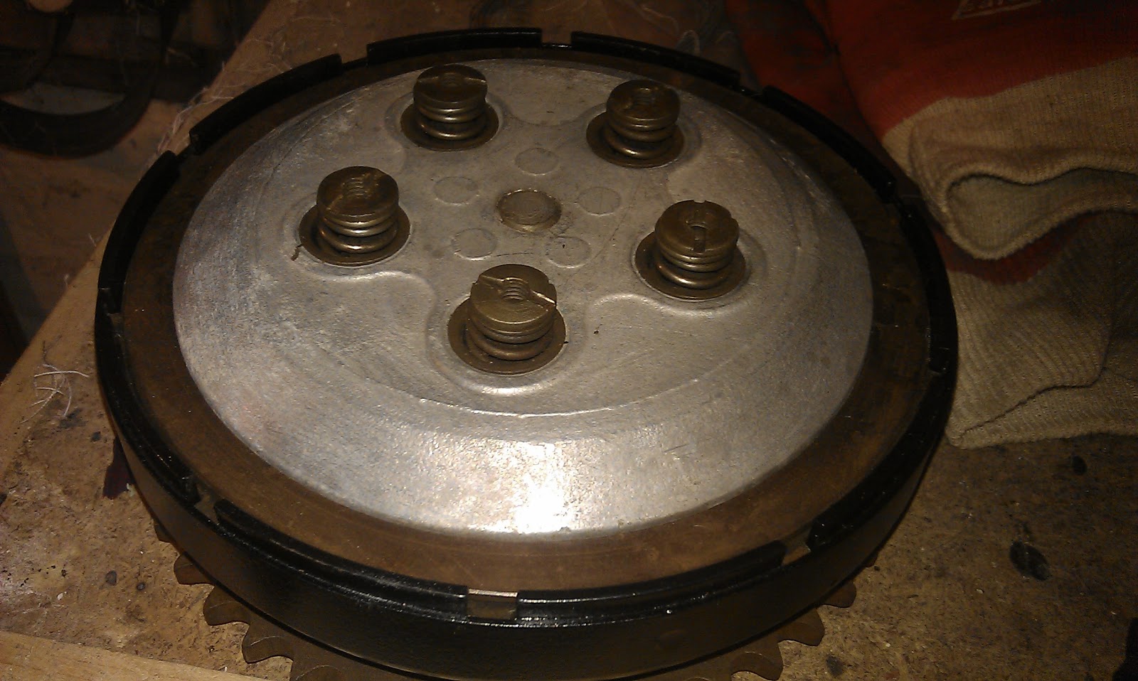
Clutch, assembled and ready for testing. Clutch nuts all ok, spring cups ok, all assembled using my clutch screwdriver, pictured in an earlier post.
Friday, 12 October 2012
Clutching at straws
The clutch has resided at the bottom of the tea chest for almost a year. I think this is the only picture i have of it, sitting on the right of the shot in it's dome. Now I know what it is, it looks like an Ariel clutch though most of the special nuts are missing - but they were soon found in the box of miscellaneous fasteners.
However, since I need to finally face up to the horror that is contained in the gearbox i.e. the long search for a replacement case and mainshaft, I need to get to grips with the clutch and get it fitted.
So dragging it out, what do we have?
Here is the pressure plate, grubby but sound, with all its cups, springs and nuts. All ship-shape & Bristol fashion.
That mangled mess in the background is the clutch centre nut and the tab washer. That is for the bin.
Here are the plates. One plain plate is missing; the others are mostly OK (no corks missing or horrendously worn) but will relining eventually. The cork protrudes above each plate in the range 1/32" - 1/16" - the plate thickness is about 1/16".
Hmmm... clutch centre. Ugly.
Hmmm... clutch centre. More ugliness. The splines are very worn and I wonder whether we have a bearing or thrust washer problem that is allowing the centre to rub on the basket screw heads.
Basket/sprocket flange & thrust washers. No evidence of the centre rubbing here? Wierd. Bearing & thrust washers look ok, but most of the needle rollers are missing. Couple of screws missing too.
Here are the pressure plate slots in the basket - not much wear here.
And here is the sprocket. Again, looking good.
Now, we need:
- tab washers
- plates
- needle rollers
- maybe a new centre
- a set of basket flange screws
Let see who's got what...
Labels:
AOMCC,
Ariel,
BA,
Burman,
classic bike,
classic motorcycle,
clutch,
cork,
restoration,
Square Four
Back to the gearbox
Eager fans might remember the Gearbox Woes post from a while back, where I was flapping about the fact that the gearbox I had received in the Ariel kit appeared to be the wrong part number, probably from a twin or a VB, and that possibly the casing was wrong and the mainshaft too.
You might also remember that I concocted a plan to test the theory in a dummy build, to look at the chain alignments. Got all that?
Well, now that the engine is in manageable chunks, we can lift it into position in the frame and see if the sprockets line up.
To do that, we have to release the front engine plates since the curve in the crankcases means that it will not drop in from the top. Releasing these plates means that the lower frame rails are no longer tied to the front down tube and the frame is allowed to spring open - not a comfortable state of affairs, so a little support is needed from a box underneath.
With the bottom end in place, we can put all the engine studs back in position and begin to settle the engine & gearbox into position.
We swung the gearbox out of the bottom lug, since we believed that the modification Ariel had Messrs. Burman make for the Square Four was to machine the top & bottom lugs with a different offset. This proved not to be the case, and the gearbox swung back in with not problem.
We know from the parts lists that the Square Four carries different gearbox casing & mainshaft part numbers; My theory is that since the SQ4 uses a 4.00" (WM3 rim) rear tyre, and the twins and singles a 3.25" or 3.50" (WM2 rim), then the gearbox sprocket must be 1/4" further outboard of the centreline, and the mainshaft must be longer to allow the clutch to maintain it's position in relation to the gearbox sprocket. To accommodate the different widths of the tyres, see? If the SQ4 engine is wider than the twins (it is clearly wider than the singles) then the mainshaft must be even longer.
But is it? having put it all back together, we find that the gearbox sprocket appears to align with the rear wheel sprocket (as we had seen months ago) and the clutch journal on the mainshaft appears to sit in the right place in the primary drive casing.
Promising? we need to sort out the clutch to find out.
More later.
Labels:
Ariel,
BA,
barrel,
Burman,
classic bike,
classic motorcycle,
clutch,
engine,
restoration,
Square Four,
tyres,
WM2,
WM3
Wednesday, 10 October 2012
Coming apart at the seams
Well, inspired by Mr. Frank Westworth and his tales of Thor, King of Hammers I have been caressing dear Amelias fine casings and she has finally agreed to show me her most intimate areas.
If you remember, I had released all the head fastenings and had summarily failed to separate the head from the barrel. At the suggestion of the ever helpful Brenton Roy, I released the barrel nuts which of course meant stripping down the timing chest, which all went very well.
So, one lunchtime I took hold of Amelia's head, and proceeded to lightly tap around the barrel base flange with my handly mallet, hide face of course.
Slowly, the barrel came free and I was able to lift it, supporting the pistons on timber bearers as I went. What was revealed was quite happy, as far as I can see - nothing has been measured yet. However, someone has been in there:
As evidenced by the single shiny piston! I'm not sure what is going on there but at least nothing is broken and there is no rust.
On the other side of the joint, again all seems well, but there is a lot of carbon about:
Here's each cyclinder, for the record: Number 1:
Number 2:
Number 3:
Number 4:
Next, we need to get the head off and measure up.
But first, now that we have the engine in manageable lumps, we will go and look at the gearbox again.
Friday, 5 October 2012
Can't stand the pressure...
Now, I have acquired a few bore gauges and this evening I have broken out the trusty old Moore & Wright micrometer and I have measured my oil pump. Here are the dimensions:
- Return bore diameter = 0.499" - 0.500"
- Return plunger diameter = 0.499"-0.4995"
- Feed bore diameter = 0.437"-0.438"
- Feed plunger diameter = 0.436"-0.4365"
Now, seeing as Mr Waller specified 0-1 thou clearance for the singles, I reckon my pump is in pretty good shape. I have max 2 thou clearance on the feed side and max 1 thou on the return.
The drive block is a different story. I have a block that varies 0.561-0.5635"; the 'groove' the block runs in on the feed plunger is 0.573 - up to 12 thou clearance. The return side is better, about 0.570, or max 9 thou clearance.
What do you all think of that? Good to go back in the engine?
I also took the opportunity to flatten the mating face - you will recall there were some little wobbles on the thin bottom edge. All gone now:
Wednesday, 3 October 2012
Feeling Pumped Now...
Except that, having removed the cyclinder base nuts in the hope that I can lift the cylinder and head together and then knock the head off from inside one of the cylinders, the block still won't shift.
So I try and turn the engine over in the vain hope that compression will break a weak base gasket joint, and then realise that as I have removed the dynamo the primary chain effectively jams the camshaft in place and I can't get it to turn over at all.
So, I must finish the job of dismantling the timing gear and the oil pump.
As I mentioned a day or two ago, the oil pump tab washers are not done up:
Not that you can see them very well in that picture. However, the pump comes off without any drama, though it is pretty tight on the studs. Here's the pump body, nicely marked '51, so it's probably the original. Slightly wobbly surface near the bottom edge:
Here are the plungers, nothing too nasty there. Some wear and light scoring - we will see what they look like with a micrometer on them later. I have nothing at the moment to measure the bores, and I will have to look at what I think the clearances ought to be since the only data I can find in Mr. Waller's book is for the singles.
Lastly, here is the whole pump ready for inspection. The check valve caps seem very stiff and whilst they appear to work I am reluctant to remove them. I really should inspect them and their seats though.
Subscribe to:
Posts (Atom)