
Sunday, 11 October 2020

W/NG - Cylinder Head

Now that the barrel is back on and the engine is timed, it is high time I started on the cylinder head. I've stripped it and done a bit of cleaning, and I know the exhaust valve and guide are very worn so I've got some new ones from AOMCC Singles spares. My plan is to get the paint on the head on and setting while I build the primary side, and I have checked over the clutch and ordered some parts from AOMCC Gearbox Spares to allow that to happen, but of course I need to do all the manual work (fitting the valve guides, grinding the valves and probably fitting them) to avoid damaging paint which will probably be soft for quite a while.

The head was pretty filthy, and after stripping it went in the parts washer for a bit of a clean.


My first job was to put a taper on the inlet valve guide, which for some reason didn't have one. These are iron and machine very easily:


Still on the lathe, I made a drift out of some scrap 3/4" bar to support the mouth of the guide while I knocked them in to the warm cylinder head


With the guides in we can have a look at the valve seats. Here, I'm using the traditional 'sucker on a stick' to turn the valves against the seat - there is a smear of coarse grinding paste on the seat.


Another variation on this themes is a bit quicker, and not dissimilar to the suggestion in the manual - in terms of driving the valve stem rather than the head:


However you do it, once you have a continuous grey band around the seat with coarse paste you can improve the sealing capability with fine paste. It should end up something like this:


Now that the valve seats are good and I know that I can assemble the head after painting, I'll start cleaning up. I'll work it all over with a range of wire brushes:


But first off, let's get that greasy head back in the cleaning tank, and give it a dose of brushes and paraffin. I usually do this before I have to go off and do something else, like sleep, have dinner or do some building work so the parts have a chance to dry - this doesn't happen so well in the winter, so I sometimes get the propane torch out and dry them with that.
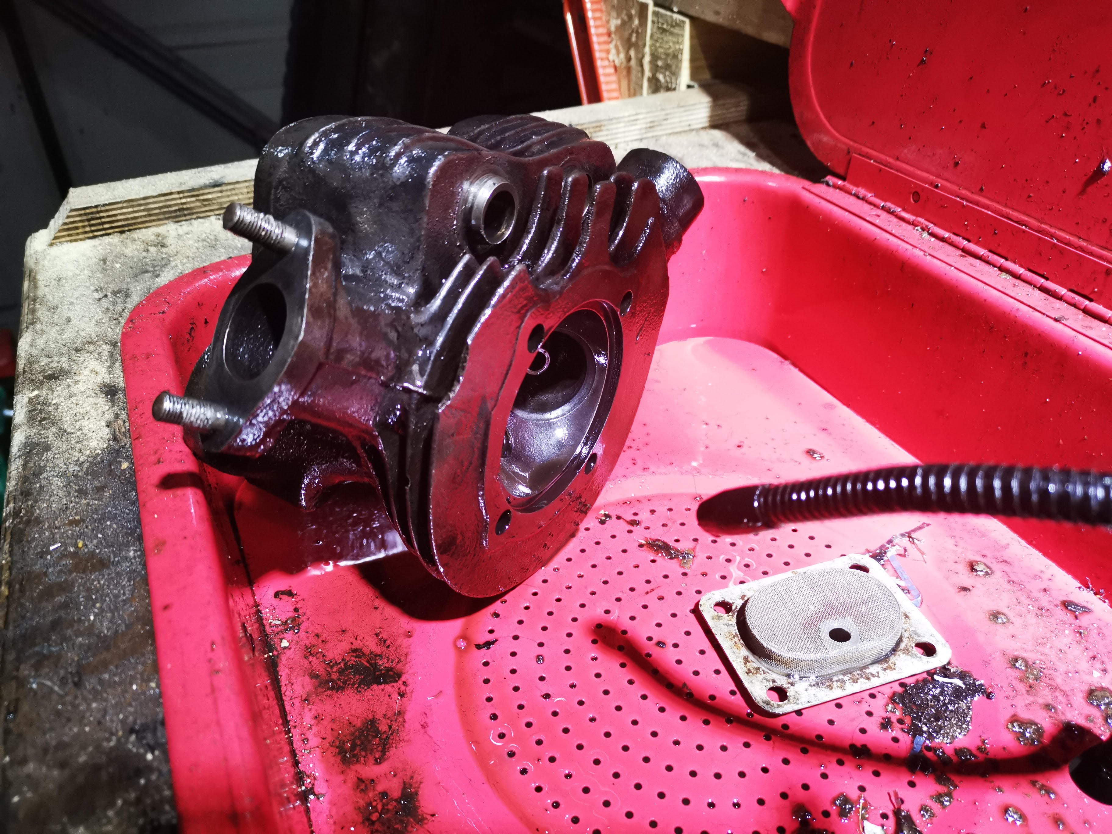

I'm using the same brushing engine paint that I put on the barrel - time will tell if that was a good idea as it is only rated to 200°C, but my temperature testing with the aluminium-head Square Four does not reach that figure. We will have to see what a thrashed iron head will do.


For the record, I put a couple of coats on the head on the 11th October. It dries in a couple of hours, but I will wait a day or two before starting to assemble it.


Post script: as of November 2022, after a fairly active and very hot summer, the paint is still intact and is showing no signs of distress. 

Sunday, 4 October 2020

W/NG - Barrel & Piston

The piston that came out of the W/NG surprised a few people. It looked like it had been wire wound at some point in it's life. It was flat-topped and had an oil control ring, both features that differ from standard.


Here's a new +0.040" Ariel piston - new old stock, still in it's original wrapping, from AOMCC singles spares. You'll see it has a raised crown and three compression rings.


The old piston was not in a happy place when it came out. The top ring was in at least three pieces - at least, I found three pieces. Not enough to make a whole ring...


The small end was also in a pretty bad way and in fact the rod eye turned out to be oval. The bush had no oil slot cut in it either.


I had the barrel rebored and honed to suit the new piston by L.A. Whitmore of Briston, Norfolk - an excellent little company which unfortunately is no more. The rebore took out most of the wear.


Much later, after I had finished the bottom end I cleaned up the barrel using my bench-mounted and my flexible wire wheels. There is actually a fin repair here as well - that must have been done in Italy.


I followed this with two coats of engine enamel from Paints R Us which appears to be excellent. We'll see when it has been in service for a bit.


For my next trick, ladies and gentlemen, I will replace the barrel studs after cleaning them on the wheel. I've put them in with Loctite 243 medium strength thread locker.


I need to check the rings. They are all showing a 0.012" gap - rather large, but well with Ariel's 0.030" limit and they are very difficult to measure as they are cut at an oblique angle and consequently any sideways movement opens the gap.


Next, I'll check the fit of the gudgeon pin in the small end. It slides in easily with no rattle; as I would hope. Alpha Bearings reamed this to Ariel specification and made a bush to suit the small end eye.


Five minutes with the Rothenburger has the piston warm enough to receive the pin and a few seconds later it is on. Next job is to fit the circlip - but cover the crankcase mouth before you try. The circlip is bound to ping off somewhere and the last place you want it is in the crankcase.


Don't try this delicate operation without gloves if the piston is still warm, and make 100% sure the circlip is seated correctly:


I don't have a piston ring compressor - I maybe should have bought one but ever since building BMC A series engines when I was much, much younger I have used this approach - a strip of tin and a ty-wrap. Works a treat if you get the tension on the ty-wrap just right for the barrel to push the tin down and off the rings, and it's dead cheap for when you need four of them.


See? all fitted with no drama, though since writing this I remembered I had intended to fit the engine plate covers before the barrel went on - access is a bit more restricted now.


That's Morris SAE50 in the bore. Next job is to time the ignition, finish fitting the magdyno and the chain cover and start preparing the cylinder head.


W/NG - Oil Pump

 Whilst I have no problems with the original 1942 oil pump, it pays to have a look when you have something apart.


All I have done with the pump is to clean it, measure it and function test it. Both supply and return plungers are within tolerance, as are their bores, and the check valves are working.


I've oiled it and refitted it with a new gasket. These eventually show patent number 325226. I wonder when the patent was granted?

Friday, 2 October 2020

W/NG - Assembling the bottom end - again...

So, a bit of spare time arrives and I have the camshaft, the cam bush, a 3/4" reamer and a gasket set. Let the bottom end rebuild commence!

First, it's back to the Rothenburger to remove and replace the bush, which I can do in one heat cycle. I'm careful to avoid the new bearing. I knock the new bush into the hot cases, driving the old bush out as I do it - a simple operation when you have enough heat.


Whilst that is cooling, let's look at the camshaft. The principle reason for replacing the camshaft is because the inner journal is badly worn. I reached out to the AOMCC Facebook community and came up with this camshaft, which is actually the profile used for the sidevalve machines. You can see it has a much longer duration than the Ariel F cam normally fitted (the one on the right), but it has the same base circle diameter. This means I will get more fuel in and and exhaust out again, and make more power but I won't have to change the followers or the pushrods.


Another problem solved by the AOMCC is the knackered half time pinion, the one at the front of the picture. A member kindly sent me the one behind, which looks unused.


Coming back to the crankcase camshaft bearings which I fitted earlier. When you buy a bush it is usually undersize, and this was no exception. It needed reaming to size, whilst aligned with the bearing in the timing chest - so I used the timing chest bearing as a guide whilst reaming the crankcase end bearing. In this next picture I have the timing chest bolted in place and a 3/4" round bar passed through both bearings to demonstrate their alignment - the bar turns smoothly and freely.


This next picture shows a block of wood I use to support the crankcase whilst working on it. The cam follower pin, crankcase nose etc. fits in the hole.


Before I assembled the engine, I fitted the camshaft so that I could prove the bearings. The camshaft turned smoothly and with no wobble, so I proceeded to dismantle it all again and to assemble the crankshaft into the cases, and to bolt the cases together.


I replaced the assembled cases in the frame and assembled the engine plates. Now that I had the crankcase held securely, I refitted the oil purifier with some Loctite 243, as suggested by Chris Williams at Alpha Bearings. A lot of folks really struggle to get these out and they often come out in pieces; I have had this one out before (and cleaned it before), so it was quite easy, but I was surprised to find it had quite a bit of sludge in it. Chris's point was that they might be difficult to get out, but if they come out when the engine is running the crankcases will be scrap.


Once that was back in, I took the opportunity to use the oil can to pump some oil into the end of the crankshaft, and eventually I saw it emerge around the big end proving that the oil ways were aligned.

Now, I could fit the new half time pinion & camshaft and set the valve timing.


I had a look at the cam followers and selected the best two. The inlet one is quite worn and I should really replace it.


Before I put the timing cover in place I need to fit the magdyno. Before I did that, I cleaned up the slip ring which was a bit mucky.


Here's a new felt seal for the magneto drive:


Next, I fitted the timing gear case with it's small gasket, and added the large gasket with Threebond 1215:


I fitted the timing gear cover and rotated the engine several times to ensure the new gears were quiet and free, adding the camshaft magneto sprocket and the magneto chain, nominally tensioned at this point. I'll finalise that when the barrel is on and I can set the timing.


Since we are nearing the end of activity from this side of the bike, I'll refit the mudguard bracket to the engine plate. The original bolt fitted here looked like it had had an M8 nut forced over a BSC thread, and both were scrap. This is a new stainless 5/16" bolt & nut.


With that done, I can fit the oil tank, hook up the oil lines and fit the oil pump.


Next, I need to clean and paint the barrel, fit the barrel & piston and set the ignition timing. Then I will close up the magneto drive having set the chain tension; I'll then inspect the clutch before I finish building the head. I know that I have to make a valve guide drift and paint the head, and possibly give the valve seats some attention - I'll do that while I wait for the clutch tab washers, nut and any other components I find damaged.

Friday, 18 September 2020

W/NG - Assembling the bottom end

I said the next step was to sort out the camshaft, and it was. The reason for that was that I wanted to replace the camshaft bush in the timing side crankcase before the crankcase halves went together and I have done that, because I have found the camshaft and I know what diameter the journal is - I'm confident that the bush can go in as-is, and not need reaming.

So without further ado I can clean the bearing journals and use the Rothenburger MAPP torch to warm up the cases and drop the bearings in, with their spacer and circlip on the drive side.


The crankshaft has been away at Alpha Bearings in Dudley, the UK's premier supplier of big ends for classic motorcycles who have replaced the big end and realigned the crankshaft at what would have been a very good price (and with a one-week turnaround) had the small end eye not turned out to be oval. I was aware that it was very worn and for some reason had no oil hole. The crank came back from Alpha true to less than 0.001" and looking excellent:


The small end eye now has it's lubrication slot. I had a small worry when I thought the mainshaft was not correctly pressed in - though Alpha's had not touched the shafts:


I spoke to Alpha and several people in the club about this suspecting that I knew the answer - it is a taper fit. Alpha explained that if this gap were absent, you could not be sure the taper was pulled up correctly - so that's another one for the memory bank. The AOMCC audience all concurred, so I am happy again.

So next, we are into shimming the crankshaft for the prescribed 0.008-0.012" endfloat. This is the set up I used - the DTI is actually attached to a magnetic stand on the vice anvil, and the heavy crankcase assembly is just sitting on the bench. Not ideal, but I found that if I move the crankshaft against the case using a twisting motion with a screwdriver (flywheel to inner case wall), that cases will not move at all.

In this way, I found that I had a total of 1.4 mm endfloat with no shims. That's about 0.055".


That's a start, but we need the correct endfloat with the rod in the centre of the crankcases. To do that, I used a bore gauge to establish a position where the rod to crankcase measurement was equal on both sides and measured the end float from this position.


I have some 0.3 mm (0.012") and some 0.5 mm (0.020") shims, of 26 mm ID. Time for some calculations:


That leaves me with 0.22 mm end float, or 0.0086". Perfect.


I bolted up the crankcase halves sealing the joint with Threebond 1215 and assembled the cases into the frame, fixing the front engine plates loosely onto the crankcases and then dropping the lot into the frame, retaining it with the single 1/2" stud at the bottom of the down tube. 

When you start on the rear engine plates, you do the drive side first, with two studs into the engine and hold the plate to the frame on the gearbox top stud, then pass the footrest bar in. If you don't do it this way you will never get the spacer in.


When that is done you can put the rest of the bolts and studs in with the timing side plate and the magneto platform. If you look closely you will see the bash plate fitted, though you cannot finally bolt this in place if you have not put the sump plate on.


You can see why the magneto platform needs those extra studs and bolts to stop it flapping about.


I made an earth wire for the magneto:


With it all tightened up, I did some trials with the timing case. Turning the engine over with the camshaft, rockers and half time pinion in place sounded awful, so I had to investigate.


That pinion is knackered. I also realised that the camshaft bush that measured up OK was actually oval - I should have looked for that before. It was OK in one direction but when I looked at 90° to the original measurement I could see it was quite worn.

The next step is to pull the engine out again, replace the camshaft bush and reassemble with a new half time pinion.