
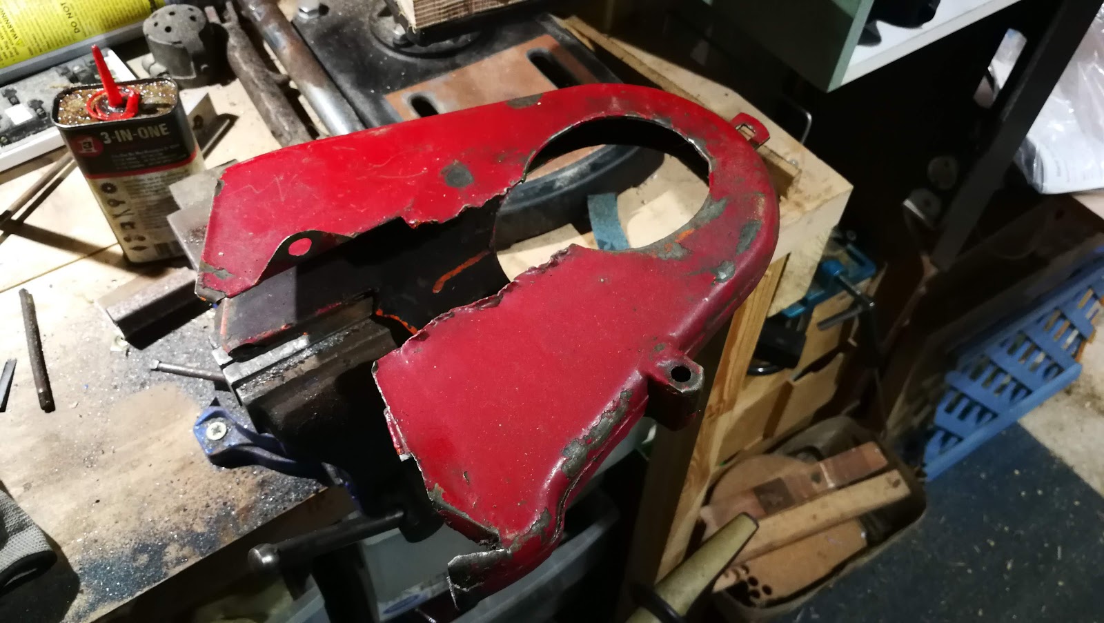
Moving on, we can start on the repair of the front section of the chain guard. This is a bit mangled:


Someone has modified it (with a tin opener) so that it can be removed without taking off the gearbox sprocket.

I don't understand this though:

This is what it is supposed to look like. These pictures are from the excellent members of the AOMCC:


You can see in this last picture, the position of the chain oiler. This is the bit that has been cut out of my mangled example, so we will need to re-create it. Mick D sent me these dimensions:
Mick says this is a 1" hole. I have the grommet from Drags:

Here's a view of the chainguard in situ - that's the chain oil pipe you can see there:

So, on to sorting it all out. Some heat and a hammer has this area flat again:

Heat and hammer again, but this activity only serves to reveal that we will have to cut this lot out:

Five minutes with a pair of aviation snips has cleaned this up. We can now find a bit of sheet to let in:

This bit will need cutting out:

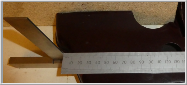
Sanding off the paint allows us to measure the material thickness with the micrometer. It's 0.043", about 18 SWG or about 1 mm thick.

Now, we'll need a pattern to cut a bit of 18 SWG sheet. We can do that with a bit of paper and a pencil - we'll just draw around the other, good side to get the curve around the swinging arm, and we can use the geometry of the main shaft hole to construct the missing curve there.

The chain guard fits around the horizontal frame gusset, which is accommodated in two slots above the 'swinging arm curve'. Luckily, there is enough metal from these slots to show us where they are.
In the end, we have this little sketch.

Now, we glue that to a sheet of 18 SWG and cut it out with snips and a file. It doesn't want to be too precise, as it needs to be 'fitted' to the job. Then, I put a 2 mm flange on the end of the repair section, around the main shaft hole to match the flange on the original part. That will make the face much more rigid.
In the next picture, the chainguard has a chunk of oak, 1" thick, stuck inside it so we can secure it in the vice. I've trued the lower edge of the cut out area with my hammer, and straightened the cut edge with a file. You'll notice the top edge is still quite bent - I will address that next. I've also messed up the flange at the bottom there, it needs to come in a bit more.

See the little blue and red crescents in the picture? For those that were wondering, they are magnets holding the repair section in place. Here's another magnet, showing the position of the grommet hole:

Ready for welding:


Butt welding with TIG in 18 swg. Set at 25 A with 5 l/min argon:

There are a few points where I need to fill holes I'd blown in it, but generally not too bad. Back side shows good penetration.

Before we go any further, we will do a trial fit and take some more pictures, to understand where the guard is near the frame and other components.

Next, we are going to mark out and cut the hole for the chain oiler grommet. The oiler pipe goes vertically down the triangular gap in the middle of this picture - the grommet position is quite critical:

Using Mick D's dimensions, we can mark out the hole. I thought I might chain drill it and file to shape, so I have used the old-fashioned witness marks around the diameter:

I've made two more repair sections for the rearmost lower edges. We will weld these in later.

I found these step drills on eBay somewhere and they seemed to get a good write up. I decided to use the biggest one to drill the grommet hole:

They make a much better job of drilling holes in sheet metal than a conventional twist drill.
A couple more hours in the workshop sees it fully welded, dressed and protected with a layer of primer.


Someone has modified it (with a tin opener) so that it can be removed without taking off the gearbox sprocket.

I don't understand this though:

This is what it is supposed to look like. These pictures are from the excellent members of the AOMCC:


You can see in this last picture, the position of the chain oiler. This is the bit that has been cut out of my mangled example, so we will need to re-create it. Mick D sent me these dimensions:

Mick says this is a 1" hole. I have the grommet from Drags:

Here's a view of the chainguard in situ - that's the chain oil pipe you can see there:

So, on to sorting it all out. Some heat and a hammer has this area flat again:

Heat and hammer again, but this activity only serves to reveal that we will have to cut this lot out:

Five minutes with a pair of aviation snips has cleaned this up. We can now find a bit of sheet to let in:

This bit will need cutting out:

Sanding off the paint allows us to measure the material thickness with the micrometer. It's 0.043", about 18 SWG or about 1 mm thick.

Now, we'll need a pattern to cut a bit of 18 SWG sheet. We can do that with a bit of paper and a pencil - we'll just draw around the other, good side to get the curve around the swinging arm, and we can use the geometry of the main shaft hole to construct the missing curve there.

The chain guard fits around the horizontal frame gusset, which is accommodated in two slots above the 'swinging arm curve'. Luckily, there is enough metal from these slots to show us where they are.
In the end, we have this little sketch.

Now, we glue that to a sheet of 18 SWG and cut it out with snips and a file. It doesn't want to be too precise, as it needs to be 'fitted' to the job. Then, I put a 2 mm flange on the end of the repair section, around the main shaft hole to match the flange on the original part. That will make the face much more rigid.
In the next picture, the chainguard has a chunk of oak, 1" thick, stuck inside it so we can secure it in the vice. I've trued the lower edge of the cut out area with my hammer, and straightened the cut edge with a file. You'll notice the top edge is still quite bent - I will address that next. I've also messed up the flange at the bottom there, it needs to come in a bit more.

See the little blue and red crescents in the picture? For those that were wondering, they are magnets holding the repair section in place. Here's another magnet, showing the position of the grommet hole:

Ready for welding:


Butt welding with TIG in 18 swg. Set at 25 A with 5 l/min argon:

There are a few points where I need to fill holes I'd blown in it, but generally not too bad. Back side shows good penetration.

Before we go any further, we will do a trial fit and take some more pictures, to understand where the guard is near the frame and other components.

Next, we are going to mark out and cut the hole for the chain oiler grommet. The oiler pipe goes vertically down the triangular gap in the middle of this picture - the grommet position is quite critical:

Using Mick D's dimensions, we can mark out the hole. I thought I might chain drill it and file to shape, so I have used the old-fashioned witness marks around the diameter:

I've made two more repair sections for the rearmost lower edges. We will weld these in later.

I found these step drills on eBay somewhere and they seemed to get a good write up. I decided to use the biggest one to drill the grommet hole:

They make a much better job of drilling holes in sheet metal than a conventional twist drill.
A couple more hours in the workshop sees it fully welded, dressed and protected with a layer of primer.


No comments:
Post a Comment