
Having got the crankshaft to a stage where I believe it is mechanically acceptable, we now turn to a vital area which is easy to overlook if you are not listening to advice or reading the books.
The ubiquitous crankshaft sludge traps - large drillings in the crankshaft which are designed to centrifugally extract solids from the circulating oil, and keep it out of harms way. These days, we use high-detergent oils and filters - the oil carries solids in suspension and the filter collects it, and there's the rub - when filling your barn find with new oil you really don't want the modern oil releasing the built up deposits of the last 50 years into your lubrication system, so you must clean the traps and banish the sludge forever before you run the engine. Never more true than if that engine belongs to an Ariel Square Four, which has very small (3/16" diameter) sludge traps.
No one wants a seized big-end, as the appearance of a connecting rod through your crankcase can be upsetting to younger viewers.
In an FH, A10 or A7 crankshaft, and many others, the sludge trap is in a large drilling through both big ends which is closed with a threaded plug at each end. The big end oil feed comes into this gallery from the timing side main bearing, and both the big ends are fed by 3/32" ports drilled directly into the gallery.

The gallery is provided with a thin tube, which acts as an oil way; until it is very blocked, the solid deposits form outside of this tube, flung away from the centre of the crankshafts rotation as you would expect. The tube features two or four holes to distribute oil to the big ends, and another hole by which it is located by one of the flywheel bolts, and one end is belled out to locate it in the large diameter of the gallery.

The tube is located at the drive side end on one of the gallery's closing plugs. The plugs are soft mild steel, very tight, often staked in and they are optimistically equipped with screw driver slots. People tell you not to bother with your impact driver - I tried it once, destroyed the slot and reached for the welder. The welder, however, is not the only way.
I started this morning with the 100 mm grinder, with a twisted wire cup brush in it, to clean up the rust (I also had it on the rear mudguard, but that is another story for another day).

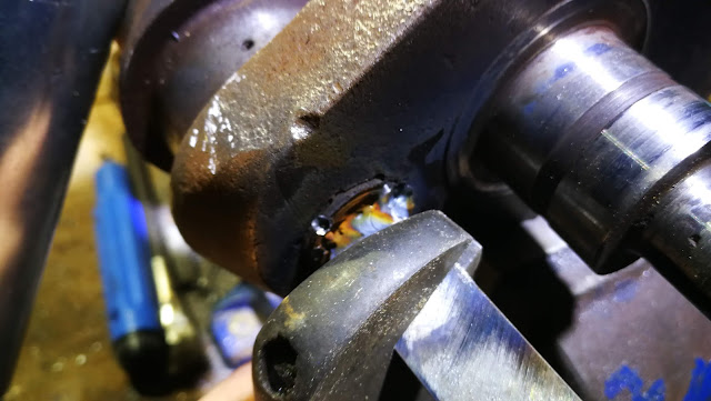
My usual approach to these is to weld a bit of 1/8" sheet into the slot. This bit of 14 swg bar was a bit small, and it wasn't clean enough:

Grab it with an adjustable and turn...
And Robert is revealed as one of your mother's siblings.

That is the timing side. The drive side, at the end of the oil way, will be worse. I loosened this plug using the 'welded bar' method, but broke the bar trying to get it out. The moral of the tale there is to take more care - make a suitable bar and weld it in to a prepared slot. Or, as I did here, drill two 1/8" holes, about 3/8" deep; grind flat the ends of two thick masonry nails (hard, and very useful), and use them as a makeshift pin spanner:

Here's another approach: Vincent van Ginneke sent me this picture; he's using a large vice to hold a 1/2" drive screwdriver bit in the sludge trap plug slot. Normally, if you try a screwdriver the bit will slip out of the slot in the plug; Vincent clamped the crank, screwdriver bit and T bar in a large vice, with just enough pressure to prevent it from dropping out and by turning the T bar a tiny bit (about 1/8th of a turn) and opening the vice also a tiny tiny bit he was able to hold enough pressure on the screw driver bit that it would stay put in the slot.

As I mentioned earlier, the drive side is worse - it's totally full:

The plug on the right is the drive side one. The nose locates the end of the sludge trap tube:

Because the tube is surrounded by solid deposits, it can be hard to shift. A hammer and a drift can be useful here - you can see the tube emerging on the left:

And that is it. That's most of the contents of the tube - the rest of it is still inside the crankshaft.

You'll want to scour that out, like this:

You also want to make sure the oil ways are clear. This is a 3/16" twist drill going through the timing side main bearing oil way, clearing the path to the sludge trap gallery. You can just see it emerging in the gallery:

You can clear the big end oil ways with a 3/32" drill.

When new, these oil ways have a 'teardrop' scooped out of the surface to distribute the oil across more of the big end width. Since these are -0.030", these 'teardrops' have long since been ground out. We can put them back with the Dremel:

When we've done, we'll polish the surface with Emery and wet'n'dry.
These are the flywheel bolts. One of them (guess which one) holds the sludge trap tube in place - that is a 3/8" BSCY intermediate tap, waiting to clean up the threads.

Both the bolts and the female threads in the crankshafts are easily cleaned up; I may replace these bolts when I assemble the engine.
The final step is to clean the remaining rusty debris from the flywheel and the crank webs, with various wire brushes. This done, I've sprayed the parts with ACF50 for storage - we'll put it all together when we come to assemble the engine.


Thanks for reading, and I hope you found it useful.
The ubiquitous crankshaft sludge traps - large drillings in the crankshaft which are designed to centrifugally extract solids from the circulating oil, and keep it out of harms way. These days, we use high-detergent oils and filters - the oil carries solids in suspension and the filter collects it, and there's the rub - when filling your barn find with new oil you really don't want the modern oil releasing the built up deposits of the last 50 years into your lubrication system, so you must clean the traps and banish the sludge forever before you run the engine. Never more true than if that engine belongs to an Ariel Square Four, which has very small (3/16" diameter) sludge traps.
No one wants a seized big-end, as the appearance of a connecting rod through your crankcase can be upsetting to younger viewers.
In an FH, A10 or A7 crankshaft, and many others, the sludge trap is in a large drilling through both big ends which is closed with a threaded plug at each end. The big end oil feed comes into this gallery from the timing side main bearing, and both the big ends are fed by 3/32" ports drilled directly into the gallery.

The gallery is provided with a thin tube, which acts as an oil way; until it is very blocked, the solid deposits form outside of this tube, flung away from the centre of the crankshafts rotation as you would expect. The tube features two or four holes to distribute oil to the big ends, and another hole by which it is located by one of the flywheel bolts, and one end is belled out to locate it in the large diameter of the gallery.

The tube is located at the drive side end on one of the gallery's closing plugs. The plugs are soft mild steel, very tight, often staked in and they are optimistically equipped with screw driver slots. People tell you not to bother with your impact driver - I tried it once, destroyed the slot and reached for the welder. The welder, however, is not the only way.
I started this morning with the 100 mm grinder, with a twisted wire cup brush in it, to clean up the rust (I also had it on the rear mudguard, but that is another story for another day).

My usual approach to these is to weld a bit of 1/8" sheet into the slot. This bit of 14 swg bar was a bit small, and it wasn't clean enough:

Grab it with an adjustable and turn...

And Robert is revealed as one of your mother's siblings.

That is the timing side. The drive side, at the end of the oil way, will be worse. I loosened this plug using the 'welded bar' method, but broke the bar trying to get it out. The moral of the tale there is to take more care - make a suitable bar and weld it in to a prepared slot. Or, as I did here, drill two 1/8" holes, about 3/8" deep; grind flat the ends of two thick masonry nails (hard, and very useful), and use them as a makeshift pin spanner:

Here's another approach: Vincent van Ginneke sent me this picture; he's using a large vice to hold a 1/2" drive screwdriver bit in the sludge trap plug slot. Normally, if you try a screwdriver the bit will slip out of the slot in the plug; Vincent clamped the crank, screwdriver bit and T bar in a large vice, with just enough pressure to prevent it from dropping out and by turning the T bar a tiny bit (about 1/8th of a turn) and opening the vice also a tiny tiny bit he was able to hold enough pressure on the screw driver bit that it would stay put in the slot.

As I mentioned earlier, the drive side is worse - it's totally full:

The plug on the right is the drive side one. The nose locates the end of the sludge trap tube:

Because the tube is surrounded by solid deposits, it can be hard to shift. A hammer and a drift can be useful here - you can see the tube emerging on the left:

And that is it. That's most of the contents of the tube - the rest of it is still inside the crankshaft.

You'll want to scour that out, like this:

You also want to make sure the oil ways are clear. This is a 3/16" twist drill going through the timing side main bearing oil way, clearing the path to the sludge trap gallery. You can just see it emerging in the gallery:

You can clear the big end oil ways with a 3/32" drill.

When new, these oil ways have a 'teardrop' scooped out of the surface to distribute the oil across more of the big end width. Since these are -0.030", these 'teardrops' have long since been ground out. We can put them back with the Dremel:

When we've done, we'll polish the surface with Emery and wet'n'dry.
These are the flywheel bolts. One of them (guess which one) holds the sludge trap tube in place - that is a 3/8" BSCY intermediate tap, waiting to clean up the threads.

Both the bolts and the female threads in the crankshafts are easily cleaned up; I may replace these bolts when I assemble the engine.
The final step is to clean the remaining rusty debris from the flywheel and the crank webs, with various wire brushes. This done, I've sprayed the parts with ACF50 for storage - we'll put it all together when we come to assemble the engine.


Thanks for reading, and I hope you found it useful.
it is very useful.Thank you for preparing this valuable article
ReplyDelete