Monday 16 September 2024

Mini-Lathe - torque upgrade

 Inspired by Ted Hansen's book, I resolved to increase the torque available at the chuck using a smaller motor pulley.


Ted provides all the details of how to make a new pulley in his book. However I reasoned that if I could learn how to specify a timing belt pulley, which would entail learning how to specify timing belts, I would probably be able to find a ready-made pulley that I could buy. The target pulley: 12 teeth, 8 mm bore, 10 mm wide.

The standard pulley has 17 teeth; moving to a 12 tooth pulley should give us a 28% torque increase.

I discovered that timing belts typically come in a variety of forms centred around the shape of the teeth. The lathe uses a belt which has a trapezoidal form, and this is called an AT format belt. The pitch of the teeth is 5 mm which makes it an AT5 belt. Is quite easy to find an AT5 format pulley with a 10 mm width. The difficult bit is that the hub is typically quite small - the one I found had a 10 mm diameter hub which I needed to bore to 8 mm. Therefore there was no room in the hub for a grub screw so the screw had to be drilled and fitted between the teeth of the pulley.

With the new pulley in place, I spent some time adjusting the level of the motor such that the belt would run in the middle of the pulley. From the dust on the end of the motor it appeared that the original pulley had allowed the belt to rub against one end and slowly abrade the belt.

With the adjustments I made then belt now runs in the centre of the new pulley which should lead to less wear. 

You can notice the change in motor speed versus the spindle speed now that the gearing has changed but you will have to wait for the next instalment to hear if this has made a difference to the depth of cut that I can successfully make.

Saturday 14 September 2024

FH - cylinder head refurbishment

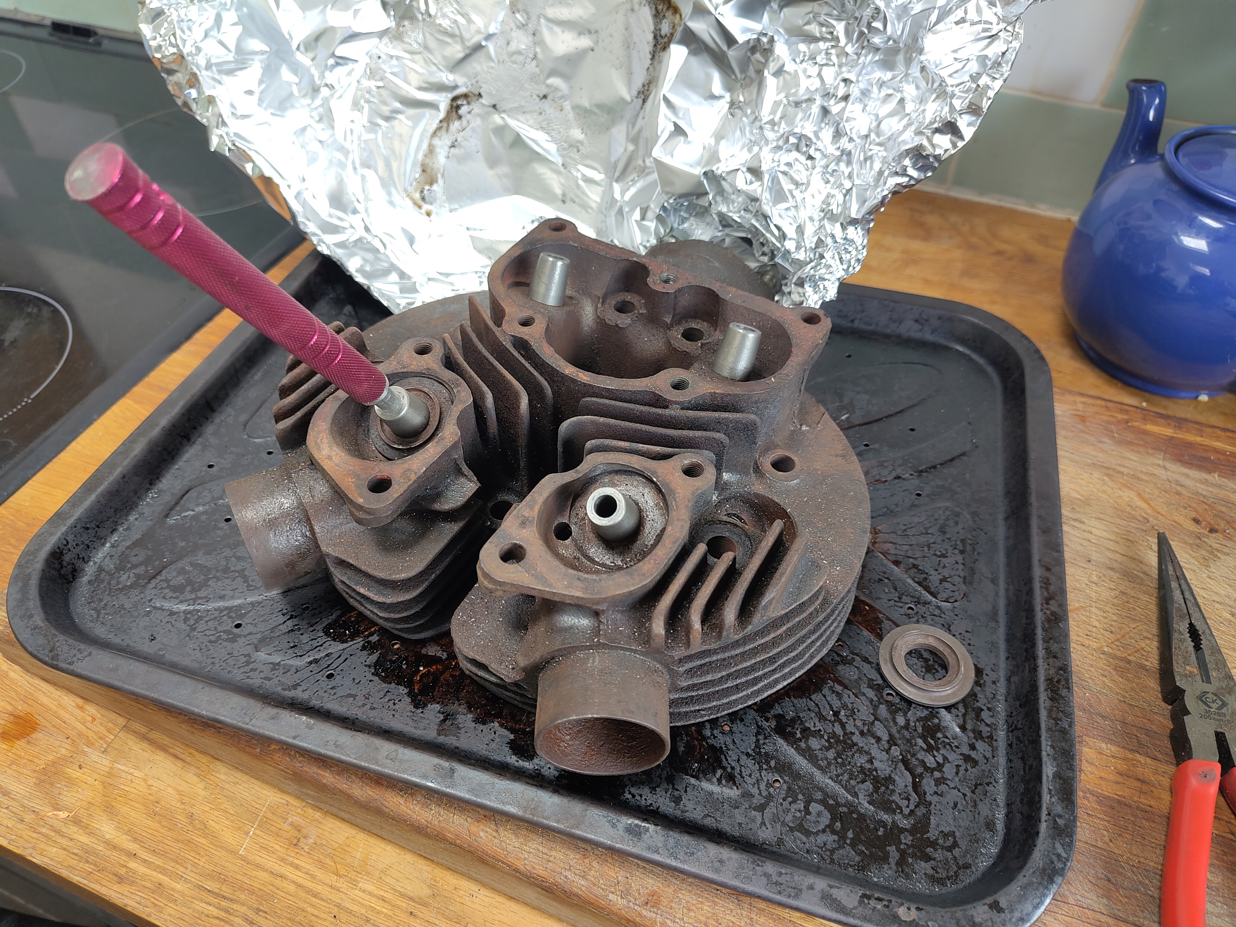
 Inspecting the cylinder head of the Huntmaster revealed that the valves and particularly the guides were very poor shape. There was 2 mm of movement at the edge of the valves when they were in the open position - so they were going to have to come out.

As you can see a lot of carbon came out with them.


Feked provided a set of valves, guides and springs at a very decent price. I guess the fact that these are BSA A10 parts provides some economy of scale.


The new guides are 0.565" diameter; the old ones are 0.562". Guide bores measure 0.561 - 0.5615". The most interference we would want would be 0.0015”, especially if they are cast iron guides - and even at that they would need reaming to finished size after fitting. That means the guides need to be 0.5625 - 0.563 for a 1 1/2 thou interference fit or 0.562 - 0.5625 for a 1 thou fit.

It was quite tricky to take two thou off on a lathe whose bearings allow half a thou movement on the diameter but I persisted, setting them up with the DTI in the ER25 collet chuck which worked rather well. In the end I got them down to the required diameter.

With them all done and the oven hot after a chicken and chips dinner I decided to put them in one afternoon. The valve guides spent half an hour in the freezer whilst the head spent half an hour in the oven set to maximum. In the event the infrared thermometer showed a temperature of 248° C and I was happy with that.


The guides went in relatively easily with help from a small hammer and a drift made from aluminium and bought from Feked; this was ok but I thought a little soft and probably not worth the money. I should have made one from steel.

I discovered during the process that the spring seats did actually fit around the guides and not under them. I wish I had realised that (or at least checked) before I started the work.


The valve seats were badly pocketed as you can see in the picture below. There was really no choice but to recut these and I deliberated for a while over whether to do it myself or to subcontract work to someone else. In the end I don't know why I bothered contemplating it really because it always comes down to the same thing - I'll have a go myself.


Cutting seats in a cast iron head is not reputed to be particularly difficult and indeed these relatively cheap eBay cutters did the job. They did however leave some chatter marks which I was able to refine I gently re-cutting again and again and eventually I got myself to a point where I used the grinding paste technique to remove the last marks.


After a bit of grinding with coarse and fine pastes this doesn't look too bad.


However if you look closely in both of these pictures you can see that the marks are not completely gone and not wishing to remove the head again anytime soon or worse to burn my new valves I resolved to do something better.


I made this cone on the lathe complete with a half inch UNF thread in the middle carry the same mandrels that the valve seat cutters came with. When I had mostly finished the cone on the lathe I put the mandrel with the cone fitted in the chuck and made my finishing cut on the cone to ensure that the cone was concentric with the mandrel and hence concentric with the valve guide.


That bit of cardboard in the foreground is the template with which you can cut the correct section out of the sheet of wet and dry paper. The system worked well and I was now able to fit the valves.

There's some cleaning up left to do on those gasket faces where I've overpainted a little but essentially the head is ready for fitting.

Sunday 8 September 2024

FH - preparing the primary drive

There are a lot of work faces appearing on the bike now the cylinder head is ready to go on; the timing side can be assembled once the automatic timing device is finished and the primary side can have the clutch fitted and the primary chain built up. For no particular reason I've elected to start on the primary side mainly because I don't have the bench space at the moment to do the ATC. Here I've fitted the 19 tooth standard gearbox sprocket with a spare secondary chain and torqued up the big nut.

 
The spare length of chain I had knocking about was too short so I've taken this unusual approach of wiring it through the holes in the sprocket just to allow me to use the back brake to tighten up the gearbox sprocket nut.

With that done we can start looking at fitting the inner primary case half. What's different about this bike is that it's fitted with the fully enclosed rear chain case (FERC) something I have not yet experienced on an Ariel. There are a couple of unusual mounting points, one of which is this nut which is attached to the front half of the FERC.


It's a 1/4 in CEI bolt which needs a special tab washer to retain it to the inner primary chain case casting and to prevent it coming undone, dropping into your primary drive. The special lock washer is available from Draganfly but unfortunately I forgot to order one. I've made this one out of a piece of 0.9 mm sheet steel.

Here it is with the bolt tight and the tab washer folded up.


For the record I have fitted that 1/4" BSW screw with low strength threadlock from Loctite. The castellated nut retaining the engine shaft shock absorber will need a split pin to prevent it falling off.


That's it for now; the next step will be to think about the clutch. I expect to find some parts that are in need of replacement so I'll have a look at the clutch soon to get those on order.

For now, let's just record that I fitted a new length of primary chain and an old spring link just for now. I'll have to order a new one. 


The other thing to bear in mind is that the chainwheel is rubbing on the oil catcher so I'll have to sort that out before I put primary case outer cover on.

Thursday 5 September 2024

FH - cam followers

After a 60 mile round trip on the Square Four which left me worrying about its coupling gears I decided to have another look at the cam followers in the Huntmaster. I had refinished the wearing surfaces to true them up but I knew that one of the followers had worn through the case hardening. I decided to stop messing about and get some replacement followers.

These are available as an exchange part from Draganfly Motorcycles and they came very quickly, in a couple of days. Refitting is very simple and I replaced the barrel with a layer of Wellseal on the gasket.


Before I did this however I wanted to make sure that the cams were going to be properly lubricated on startup so I used my oil can to make sure the channel under the camshaft was full of oil as you can see in the picture below.


With the barrel fitted, I could oil the followers from above:


I threw the pushrods in to start understanding how difficult they would be to fit. I once spent ages chasing a valve timing problem on the Square Four only to find that I had the pushrods in the wrong followers!