Monday, 28 January 2013

Apologies...

Apologies if there doesn't appear to be much going on, but I have been away travelling again. Last week was spent mainly in Stavanger (-7 degrees C) and Oslo (-18 degrees C) and I have only just thawed out.

When I am away working, I tend to order stuff to get busy with when I get back. This was a similar trip. I have been talking to Bernard Ashpole in Bishops Stortford about doing a few jobs on the engine. I'm going there tomorrow and hopefully the following jobs will be done:
  • soda blasting the crankcases, barrel and the original head (so I can sell it)
  • welding up the damaged fin on the barrel
  • replacing the timing side main bearings, line boring them and replacing the camshaft bush
  • tidying up the camshaft journal
I ordered the dipswitch, horn button, and the indicator switch from the VMCC - these are now stashed away. I also ordered the oil filter, which I have to make a bracket for. I'll zinc plate that when I'm done.

I've also ordered a few more parts from Acme, this time the exhaust brackets & bolts and the 5 nuts for the QD rear wheel, and the front brake cable adjuster.

I have a full set of stainless engine bolts from them, and the timing cover, primary cover, and coupling gear cover screws. All very nice, as usual, and a pleasure to deal with.


When I ordered the camshaft bush from Drags, Lee noticed that I had a battery box (the dummy Lucas GU11E) on back order - so this has now been delivered. Here it is in the tray I made earlier. 

And lastly, I have been looking at the wiring. Moved by a discussion on cable ties on the AOMCC forum (how many rivets in a BR Standard Class 5?),  I started to look closely at the wiring harness.

This discussion was so interesting that I have moved it to it's own post, here

Friday, 18 January 2013

Cast Number Plate

In response to a post on the AOMCC forum, here are some pictures of my front number plate:

 Front end view
 Rear end view

Rear end, side view

Front end, side view

Hope that helps James!

Monday, 14 January 2013

There is life in the old blog!

Well, what is new since the weekend? Well...
  • it's snowing
  • the Bantam has been out around the garden
  • Limoncello makes great Martinis
On the bike front, we are still cleaning & inspecting the engine. I've attacked a 14 mm hex socket (not a bi-hex) with a file and have made it fit the connecting rod nuts. The rods are now off and undergoing cleaning. Number 2 is nicely polished.


There are various nicks. This one is typical, but it is minor compared to the abrasion the Ariel fitters cause when they removed the flash around the forging dies:

Hopefully I will show you factory abrasion in another entry - I had cleaned it off Rod No. 2 before I thought to photograph it.

There is a nice little scratch in the cap:

The big end shells are all shot; the journals are a little undersize but are perfectly serviceabe.

All the dings polish out OK. At some point we will do a dye penetrant inspection on these just to be sure there are no cracks.

I have new AOMCC rods in the budget - I am just not yet sure whether I really need to spend the money. The state of the big ends and the mains, which despite white metal flaking were still in tolerance, suggest to me that this engine has had an easy life, though I realise this conflicts with the fact that the bores are 0.020" overbored.

Of course no amount of inspection can tell me what state the material is in - only it's service life could tell me if these rods have been fatigued enough such that they will fail in the next few years. It's a 35 bhp engine - judging by the way I ride the Bantam about Norfolk am I really likely to stress this engine? If I fit the Morgo pump will it see any shortage of lubrication? Shortage of lubrication will trash any big end, old or new - so we are down to loading & rpm...

The crankshafts have now all been cleaned out. Number 3 sludge trap was full past the big end oilway, though there is no damage to the journal or the big end so I think the engine has been lucky.

I've loosely reassembled it all in preparation for taking the bottom end for line boring. Here are the crankshafts back in place:


Here are the cases cleaned up and back together. I am debating what to do with the polishing of these.

And as an aside from the engine, I have been:
  • sketching up a wiring diagram with Microsoft Powerpoint. Currently it has six fuses, no earths (because I haven't put them in yet) and no indicators.
  • I have ordered the engine bearings from Drags
  • I have ordered a replica Lucas 529 rear lamp
  • I've ordered the engine/gearbox mounting set, the coupling gear cover studs and the primary drive screw set from Acme
But now it's back to work. I'm hoping to have a trip to London in a couple of weeks to take the engine down to Ashpoles; that depends on the bearing arriving from Drags.


Tuesday, 8 January 2013

Time for a list.

I'm getting confused, there seems to be a lot of stuff going on, lots of bits laying about, lots of work faces.
Whenever life gets like this, I like to make a list to get my head around where I am.

So the engine is more or less apart:
  • the crankcases are dismantled & roughly cleaned - the oil pick up pipe is still in, the bushes & bearings are still on. The dynamo strap is off and needs replating; the timing side bushes are still in tolerance but are flaking, so will have to be replaced. Either Bernard Ashpole or Colin Reed Apsley will do this for me. The roller bearings look good but will be replaced anyway. The camshaft bush is in tolerance but will be replaced; then there is the question of whether I polish the crankcases. I kind of like the contrast between the polished timing cover and the faded grey cases.
  • then there is the question of modifications - the Morgo gear pump, the camshaft spraybar, the valve stem seals, and the oil filter.
    • I'm thinking that the additional flow from the Morgo pump will let me flow more oil to the rocker box and down onto the camshaft, rendering the spraybar superfluous. The valve stem oil seals will help avoid that extra oil going down the valve guides. The pump will also keep the oil to those far-off journals flowing at sufficient pressure
    • The oil filter is a must to avoid the sludge traps filling up;
    • The oil cooler seems inappropriate since club wisdom suggest that the oil will not get warm enough anyway, and the cooler will not be used. The more onerous issue seems to be to get the engine heat into the oil in the first place.
  • the camshaft shows a small amount of wear on the peaks; the journal for the crankcase bush is wearing unevenly and is on the low side of acceptability. We'll probably get this reground and make a bush to suit.
  • the front crankshaft has been cleaned and a preliminary clean performed on the oil ways. The big ends refuse to be shifted - I am waiting for a thin wall socket to get them apart. The timing side journal is within tolerance and is in good shape. No.1 big end rocks a lot more than No.4; No.1 little end bush is out of position - it's protruding beyond the rod eye and the oil hole is misaligned.
  • the rear crankshaft is waiting attention; the timing side journal is within tolerance and is in good shape.

Friday, 4 January 2013

Getting to the bottom of it...

Well, last night we removed the engine again and split the cases. No great problem - oil mess on shed floor.

Not a very good pic I'm afraid. Interesting piece of debris:

It's metallic, the curved edges are as cast and the straightest edge is a fracture. We shall see no doubt.

So the cranks are out; I have started to clean up the front crank:
The timing side journal is good (dimensions shown in the Engine Tolerances page) and the rods look good too. You might recall that No. 1 small end bush is out of position and the oil hole does not line up.

The big ends feel OK, No.1 rocks considerably more than No.4. I will need to grind down my 1/4" BSW socket to allow it to fit the big end nuts - I have already mauled a tube spanner. The oil pressure relief valve had a large chunk of debris in it - rubber or carbon, I'm not sure which at the moment.

Next was the sludge traps. The plugs came out with the impact driver & I consider that a lucky break. Full of carbon though:

However, I poked a 5 mm twist drill into these and the carbon, approximately as hard as clay, was quite easy to remove.

It was obvious from the resistance, and the consistency of the goo coming out that the carbon extended down to the big end oil ways (cross drillings) and no further. At this point, the goo was very oily and no more solid came out.

When I removed the opposite plug, exactly the same sequence of events and when both were clean I was able to poke a bit of welding rod down the drillings, right through the crankshaft. 

It's not a straight hole - they are obviously drilled from either and and meet in the middle.

So, there is not much more I can do with that until I can remove the big ends. Then I can clean out the smaller big end drillings and properly clean the main bore through the middle.

I haven't really looked at the cases yet. When I removed the sump plate ('Very flat, Norfolk') there were flakes of white metal in the primordial ooze. These came from the timing side mains:
I was aware that these were shot from the movement on the nut. Now we have to find someone to replace and line-bore them!

More later.


Tuesday, 1 January 2013

Shiny Things...

Over the holidays, I've been continuing to use products from the http://www.thepolishingshop.co.uk/ to bring Amelia back to life.

I bought the 16 piece Budget Polishing Kit which contains three mops and three grades of polish:
 Budget Metal Polishing Kit 16 piece
The budget kit contains the essential three polishing steps. It removes light marks/scratches and takes you to a bright finish. There is one mop for each compound: A sisal mop for the grey Menzerna heavy cutting compound (the most coarse); a stitched cotton mop for the green Menzerna  medium compound; and an unstitched cotton mop for the blue Menzerna fine compound. This keeps the polishing simple & easy - you load the compound into the mop and you only use that mop with that compound. You work through the compounds one by one, completing each step before moving on to the next.

The products these guys offer are great value and the arrive very quickly.

Here is the coupling gear cover after going through all the steps:


I soon found that to deal with the aged alloy to my satisfaction I also needed the Abrasive Compound Kit, which contains three more mops and three grades of Abrasive, from 80 to 300 grit:
Abrasive Compound Kit 8 piece
This is the set up I use. The goggles, mask,gloves and an apron are essential, as this process is messy. That mop is loaded with 150 grit and the primary cover has been polished with it.


Here's a shot of the timing cover I did a while ago. It illustrates one of the problems with polishing - it is not as shiny as the coupling gear cover! You have to make an effort to get the parts to the same degree of polish, especially if they are going to be seen out together! Sounds a bit like me & my teenage daughter...


And a 'before' shot. This graphically illustrates why you need the abrasive - the polish will never shift that oxidation:

Here's the primary cover and the number plate:

So there you go. It's easy, if messy, but it saves a lot of money since it is quite time consuming - very satisfying though!

Friday, 28 December 2012

Very Flat, Norfolk

We can muse over what the oft-quoted Noel Coward meant by this line from 'Private Lives', which premiered at the Edinburgh King's Theatre 1930. However, keen observers and students of geography will know that Norfolk, whilst undeniably low lying compared to some parts of the country is positively undulating when compared to others, notably the Fens, at least in places.

Undulating is also a word that could be used to describe Amelia's sump plate, which won't be doing any sealing anytime soon:


Anyone got a spare one?

Wednesday, 26 December 2012

Ever deeper - Coupling Gears and Bearings

Under the guise of clearing out the workshop (I was - I was trying to finish off the primary case polishing, but Mrs H was surfing and wanted some Boxing Day P&Q) I ventured into the shed to retrieve the coupling gear cover.

The idea is that once the coupling gear cover is off, I can polish it and the primary case.

The nuts and screws came out relatively easily, but the cover was a b****r to get off, as we say in Norfolk.

Turns out that the cover has a steel locating sleeve around two of the studs, which corrode and resist the removal of the cover. A few minutes with the hide mallet and a soft drift had it shifted (seized at the front, where the steel sleeve meets the weather).

Anyhow, here it is, off:


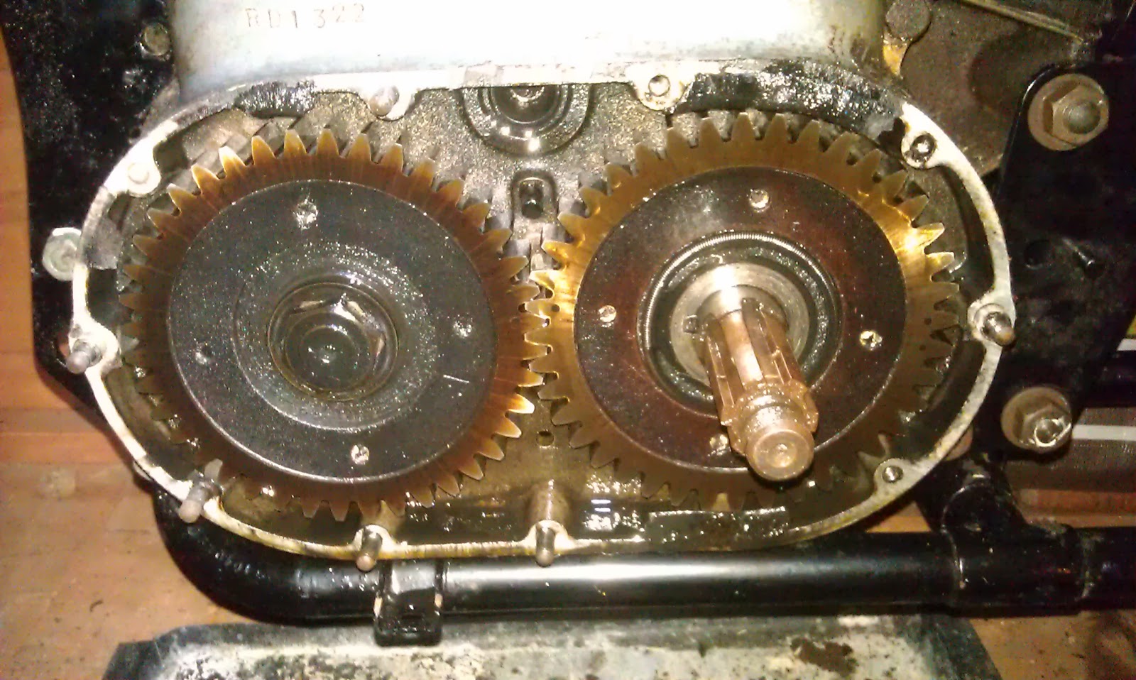
No drama there, all present and correct - though I expected the coupling cover main bearing to slide out of its journal and stay on the shaft. The peculiar face-type oil seal is cratered - bits of the seal are completely missing.


Here is the cover, complete with bearing. There is a fair bit of gunge in there, which will be ferrous material from the wear on the gears I expect.

The bearing is in there, and for some reason refuses to turn. The story is that this bearing, which is essentially similar to the other drive side main roller bearings, has a inner race which is 0.001" smaller than the roller bearing in the crankcase, so that the corresponding journal on the crankshaft is also smaller. 

This means that when the engine is assembled, the smaller outer journal (the one for the coupling gear cover bearing) will pass through the main bearing in the crankcase.

This bearing is also lipped on the outside of the outer race. It's not entirely clear why they did this, since the crankshaft is located axially at the timing side.

Anyhow, this went back into the workshop to be cleaned up. It turned out that someone had fitted two paper gaskets to this cover for some reason.

The bearing came out with some gentle persuasion (a hammer and a socket in the time honoured fashion) but a look inside the outer race revealed it was junk:

A massive pit and some odd wear marks in the outer race. There were possibly some wear marks on the inner race as well, but we need to look further before passing judgement on those. 
All in all, a jolly evening's work.


Shock Horror!!!

To get further into the engine, we have to remove the crankshaft shock absorber. This consists of a sleeve splined to the rear crankshaft and hence driven by it. The sleeve has a external spline as well, and a section of it's length which is a plain bearing surface. The engine sprocket runs on this plain section, and is machined with a face cam. The corresponding cam profile is machined onto a further part, which is splined internally and is driven by the sleeve on the crankshaft.

In order for the crankshaft to drive the engine sprocket, and to prevent the face cams from riding over each other (resulting in no drive) the whole assembly is held together by a heavy spring.
 

Hence if the system is running smoothly, the cams are held together by the spring - but if there is a sudden high torque the cams are free to slide over one another and compress the spring. This thus forms a transmission shock absorber, rather like the rubber cush drives commonly found in more modern machines in the centre of the clutch.


I guess that at the time these engines were designed rubbers were not able to withstand the heat & oil found in the primary drive.

Anyhow, it is all in pretty good shape, with no evidence of wear anywhere. Even the sprocket is good. It has 25 teeth by the way, just for the record. This strikes me as a little odd - Drags list 26T and 27T sprockets; my '52 Ariel Owners Guide says 24 solo and 22 sidecar; the '51 SQ4 parts book lists 22T, 23T and 24T.

Mr Waller however lists 25T, so it must be OK!

The only thing I could find at fault was the retaining nut, which is pretty mangled and the split pin was missing.


Bracketry

Brenton Roy posted this picture on the AOMCC forum to help out us poor souls restoring Mk 1 Square Fours:


It shows, rather obviously, the top of the oil tank with the breather tower, the filler and a mystery bracket.

I had no idea this bracket was there, but since I have had a mystery hole in the top of my tank I suppose I should have figured it out. Anyhow, it was a simple matter to make one out of a bit of steel strip that was laying about in the bits box:


I'll fill in that hole next time I have the welder out.

Friday, 21 December 2012

Monday, 10 December 2012

Still Cold Outside


So we have to find another job that will  bring us indoors.

I don't have many of those left now, but one thing I haven't touched is the oil tank.

Its the right tank, but it has a number of problems:
  1. The filler neck is bent, and the thread damaged on one side. It looks as though some clumsy oaf has dropped it neck down on a hard floor.
  2. The breather connection is bent, caused by said oaf probably in the same floor-dropping activity. The picture above shows this one, and the filler neck, though I had started work on it when I took this shot (as witnessed by the 38 mm socket acting as a former)
  3. The filter is missing
  4. There is a hummungous dent in the side that is hidden by the battery
The first of these little gems that I tackled was the damage to the filler neck. The bend was on one side and had splintered the crests of some of the thread away from the base material. Looking closely at this I decided that the material must be relatively hard, so I elected to normalise the metal.

Normalizing is the heating of steel to above its critical temperature followed by cooling in air. The piece is usually left somewhere warm. Normalizing is a quick method of softening a piece to the point where you can harden and temper it for use for your chosen purpose.

I used the trusty Rothenberger Superfire 2 to heat the area to bright red, and played the flame at a distance to bring the temperature down as slowly as possible.

Then, using a large socket in the vice, I placed the neck over the socket to use the socket as an anvil. I used a 38 mm socket, which supports the neck nicely and is a close fit.

With the material cooled & annealed, I was able to push the bent neck back into shape with a variety of drifts & chisels. This went very well, which just left me with the thread to fix.

I did this in two stages, possible needlessly. I started by grinding out the damaged part with the Dremel, since it was confined to about 15 degrees of the full circumference and maybe 6-7 pitches. I cleaned it up using a 1/2" CEI plug tap as a chaser.

Looking backward, I could probably have saved more of the original material if I had started with the tap. Still, the cap will now happily go all the way down to the seal!

The next job I had to tackle was the breather tower. I had a very good picture of what this is supposed to look like from (The Ever Helpful) Brenton Roy of the AOMCC.

As you can see from the pictures, the delightful minaret shape of the breather was a pale shadow of it's former self after the short bungee-less jump onto the garage floor, and I was afraid that much grief provided by attempting to cold form it back into shape would:
  • Squash the tube flat
  • crack the material of the 'minaret'
So, I figured some hot work was called for, though at this point I hadn't decided if I might do this with the breather detached from the tank. Holding the tank by the lower mount (so I could pull up on the breather connection) I heated the breather bright red and held the little tube in a mole grip, with a suitable rod (actually a masonry nail).

I found that the tube would move from side to side quite easily once the material was hot enough, and this with some upward pressure was enought to roll the minaret up and out of it's inverted position. A couple of cycles of this and it was back to a very passable representation of it's former self.

Next job: the dent in the side.

Friday, 30 November 2012

Engine Tolerances

Today I have posted a new page, 'Engine Tolerances'. This shows a table of the dimensions and tolerances I am using to inspect the engine, and will build up as I complete the inspection.


I started by measuring the bores. I now know that Amelia's bores are 20 thou oversize, but that they are looking good with little wear.

I've measured up the pistons, rings & pins. The results are shown on the 'Engine Tolerances' page.

In line with a current topic in the AOMCC forum, I will weigh the pistons & pins - though I don't know what I will compare them with! or what I will weigh them with!

Tuesday, 27 November 2012

Back in Charge

As an aside from the engine strip, which is challenging at the moment since Amelia is still resident in the Summer House and the bottom end is in the frame, and there is precious little light to use to continue the engine strip, I have been polishing up the chain case and making the battery tray.

You'll have seen the post Battery Carrier earlier in the blog and you will know that I had no part of the battery carrier originally. You'll also know that thanks to the generosity of the Ariel Owners Club members I have been able to get all the technical details I need to make one.

So, starting with Brenton Roy's drawing, the dimensions of the GU11E battery from an old Lucas catalogue and some 16 SWG cold rolled steel sheet, we could get started.

Using the faithful Bosch jigsaw, I cut an oversize blank just to have something I could handle on the bench. These days, having failed to make myself some engineers marking blue, I mark out using a Sharpie spirit marker before witnessing in the traditional way, with a dot punch.

The next stage was to cut out the shape with the hacksaw. The 'internal' tabs (those that the screws pass through, underneath the battery carrier) I cut out with a piercing saw, starting first with a 1 mm drill at each end of the cut. 

The shape was then finished off with various files.

The holes were then centre punched and drilled 7 mm, (clearance for a 1/4" BSCy screw).

The next stage was to fit the nuts. These were 1/4" BSCy full nuts, tacked in place with the trusty MIG, and yes, those holes are noticeably triangular - hard to drill perfectly round holes in sheet metal.

The next step was to bend up the tabs. I put both halves of the chaincase in the vice to check the overall width before I did this - I didn't want to end up with the tabs out of parallel or rebending them.

Here is the raw battery tray fitted to the chaincase for the first time. The special fasteners and spacers are from Acme Stainless. It's looking good.

That is about it really. I re-cut all the threads since the welding appeared to have caused a little distortion  I draw filed the edges and deburred, and since this picture was taken I bent up that tabs that retrain the battery. Might be a problem here - I have ordered a battery from Drags but I don't have it yet.

Last thing before assemble was to paint - the usual UPol etch primer, followed by Halfords gloss black acrylic, then final assembly, and that's it. Again, stainless parts from Acme.

A few days spent in a warm room saw it packed away in a box until the bike is assembled.


Wednesday, 21 November 2012

Nasty little pit

'Poor quality castings' is a criticism often leveled at Square Four Mk1s. Here's a nice little pit in the primary case. I might fill it, but it is not going to hurt anyone.