Saturday, 14 September 2024

FH - cylinder head refurbishment

 Inspecting the cylinder head of the Huntmaster revealed that the valves and particularly the guides were very poor shape. There was 2 mm of movement at the edge of the valves when they were in the open position - so they were going to have to come out.

As you can see a lot of carbon came out with them.


Feked provided a set of valves, guides and springs at a very decent price. I guess the fact that these are BSA A10 parts provides some economy of scale.


The new guides are 0.565" diameter; the old ones are 0.562". Guide bores measure 0.561 - 0.5615". The most interference we would want would be 0.0015”, especially if they are cast iron guides - and even at that they would need reaming to finished size after fitting. That means the guides need to be 0.5625 - 0.563 for a 1 1/2 thou interference fit or 0.562 - 0.5625 for a 1 thou fit.

It was quite tricky to take two thou off on a lathe whose bearings allow half a thou movement on the diameter but I persisted, setting them up with the DTI in the ER25 collet chuck which worked rather well. In the end I got them down to the required diameter.

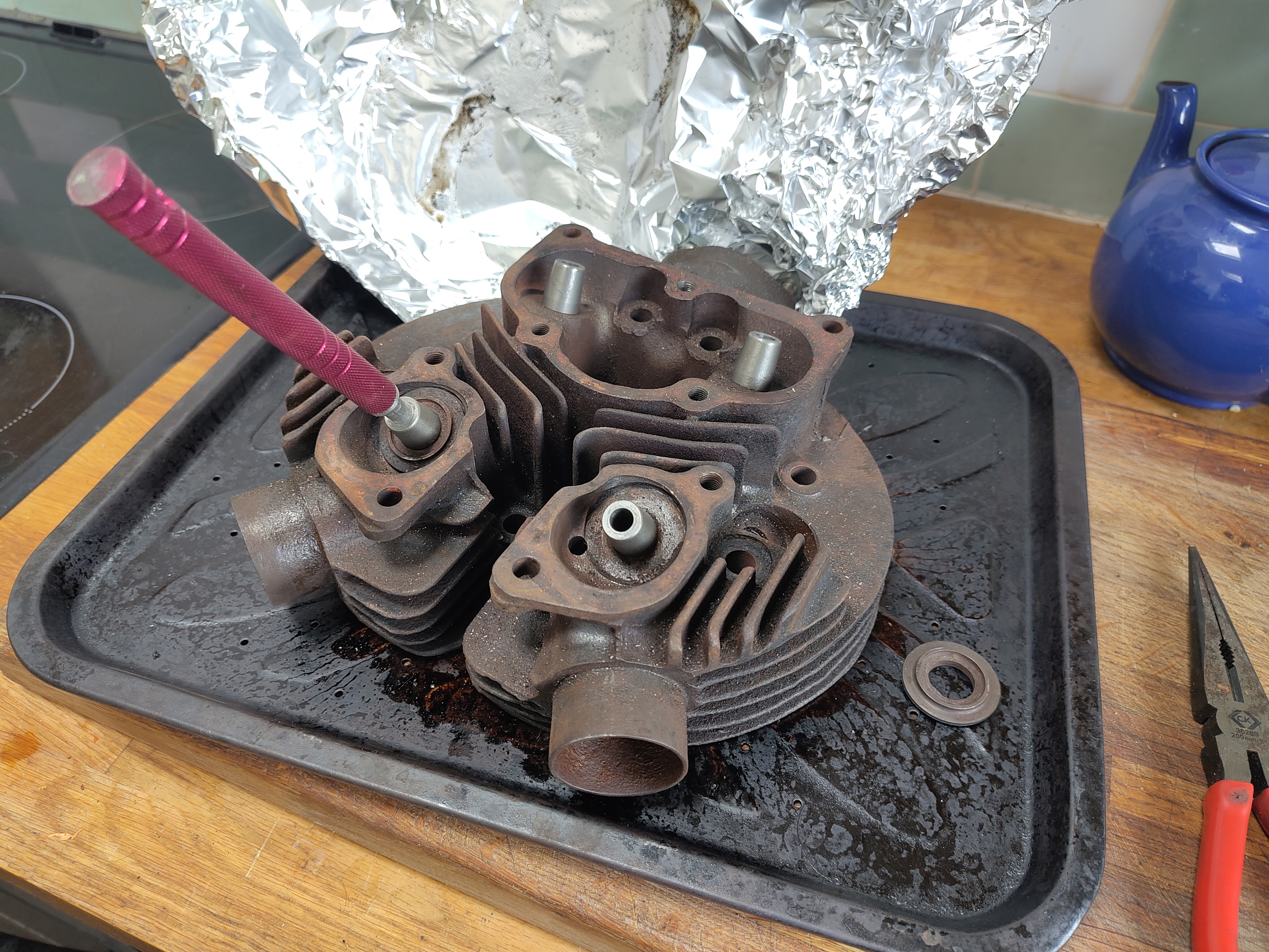
With them all done and the oven hot after a chicken and chips dinner I decided to put them in one afternoon. The valve guides spent half an hour in the freezer whilst the head spent half an hour in the oven set to maximum. In the event the infrared thermometer showed a temperature of 248° C and I was happy with that.


The guides went in relatively easily with help from a small hammer and a drift made from aluminium and bought from Feked; this was ok but I thought a little soft and probably not worth the money. I should have made one from steel.

I discovered during the process that the spring seats did actually fit around the guides and not under them. I wish I had realised that (or at least checked) before I started the work.


The valve seats were badly pocketed as you can see in the picture below. There was really no choice but to recut these and I deliberated for a while over whether to do it myself or to subcontract work to someone else. In the end I don't know why I bothered contemplating it really because it always comes down to the same thing - I'll have a go myself.


Cutting seats in a cast iron head is not reputed to be particularly difficult and indeed these relatively cheap eBay cutters did the job. They did however leave some chatter marks which I was able to refine I gently re-cutting again and again and eventually I got myself to a point where I used the grinding paste technique to remove the last marks.


After a bit of grinding with coarse and fine pastes this doesn't look too bad.


However if you look closely in both of these pictures you can see that the marks are not completely gone and not wishing to remove the head again anytime soon or worse to burn my new valves I resolved to do something better.


I made this cone on the lathe complete with a half inch UNF thread in the middle to fit the same mandrel that the valve seat cutters came with. When I had mostly finished the cone on the lathe I put the mandrel with the cone fitted in the chuck and made my finishing cut on the cone to ensure that the cone was concentric with the mandrel and hence concentric with the valve guide.


That bit of cardboard in the foreground is the template with which you can cut the correct section out of the sheet of wet and dry paper. The system worked well and I was now able to fit the valves.

There's some cleaning up left to do on those gasket faces where I've overpainted a little but essentially the head is ready for fitting.

Wednesday, 11 September 2024

FH - preparing the clutch

 Next up after the primary case is the clutch. I have the whole clutch that came with the FH kit but I've not had a look at it yet. Let's see what we have.

First of all let's have a look at the clutch centre. As expected and like most Ariel clutches that I have seen the grooves in clutch centre that carry the plain plates are deeply notched. This is useless and will have to be replaced otherwise the clutch will never release cleanly.


The rest of the clutch though is pretty good if greasy. First of all I'll clean it in paraffin tank and set it aside to dry for a day or two.


Meanwhile I bought a few bits from the AOMCC gearbox spares specialist. This includes a new clutch centre spring studs set screws for the basket and a couple of tab washers, and as usual the parts are available at a good price, are delivered very quickly and are very good quality:


When the parts I've washed are dry I've wiped them over with a blue paper towel. The clutch basket, which is of later type with friction material riveted to the basket responds well to an additional clean in a solvent.


Sunday, 8 September 2024

FH - preparing the primary drive

There are a lot of work faces appearing on the bike now the cylinder head is ready to go on; the timing side can be assembled once the automatic timing device is finished and the primary side can have the clutch fitted and the primary chain built up. For no particular reason I've elected to start on the primary side mainly because I don't have the bench space at the moment to do the ATC. Here I've fitted the 19 tooth standard gearbox sprocket with a spare secondary chain and torqued up the big nut.

 
The spare length of chain I had knocking about was too short so I've taken this unusual approach of wiring it through the holes in the sprocket just to allow me to use the back brake to tighten up the gearbox sprocket nut.

With that done we can start looking at fitting the inner primary case half. What's different about this bike is that it's fitted with the fully enclosed rear chain case (FERC) something I have not yet experienced on an Ariel. There are a couple of unusual mounting points, one of which is this nut which is attached to the front half of the FERC.


It's a 1/4 in CEI bolt which needs a special tab washer to retain it to the inner primary chain case casting and to prevent it coming undone, dropping into your primary drive. The special lock washer is available from Draganfly but unfortunately I forgot to order one. I've made this one out of a piece of 0.9 mm sheet steel.

Here it is with the bolt tight and the tab washer folded up.


For the record I have fitted that 1/4" BSW screw with low strength threadlock from Loctite. The castellated nut retaining the engine shaft shock absorber will need a split pin to prevent it falling off.


That's it for now; the next step will be to think about the clutch. I expect to find some parts that are in need of replacement so I'll have a look at the clutch soon to get those on order.

For now, let's just record that I fitted a new length of primary chain and an old spring link just for now. I'll have to order a new one. 


The other thing to bear in mind is that the chainwheel is rubbing on the oil catcher so I'll have to sort that out before I put primary case outer cover on.

Thursday, 5 September 2024

FH - cam followers

After a 60 mile round trip on the Square Four which left me worrying about its coupling gears I decided to have another look at the cam followers in the Huntmaster. I had refinished the wearing surfaces to true them up but I knew that one of the followers had worn through the case hardening. I decided to stop messing about and get some replacement followers.

These are available as an exchange part from Draganfly Motorcycles and they came very quickly, in a couple of days. Refitting is very simple and I replaced the barrel with a layer of Wellseal on the gasket.


Before I did this however I wanted to make sure that the cams were going to be properly lubricated on startup so I used my oil can to make sure the channel under the camshaft was full of oil as you can see in the picture below.


With the barrel fitted, I could oil the followers from above:


I threw the pushrods in to start understanding how difficult they would be to fit. I once spent ages chasing a valve timing problem on the Square Four only to find that I had the pushrods in the wrong followers!

Saturday, 24 August 2024

FH - rocker box refurbishment

With the cylinder head coming on, it’s time to take a look at the rocker box. We won’t be doing too much, as a number of folk have told me how a BSA A10 rocker box fits straight on and is a much better design - but I don’t have one of those.

We’ll start by stripping out the rocker shafts and cleaning the box.

While the lathe is in action, we’ll replace the 5/16" BSW stud that wasn’t holding the cover on - the covers are held on with a special 1/4" CEI sleeve nut. What we need is a stepped stud, like the original in the inlet side but with a 5/16" BSW thread to go in the aluminium casting. Somebody has already recut the thread in the casting to suit the replacement stud.

We'll start with a bit of 5/16" mild steel round bar. Because it's 1/4" in diameter for most of its length we'll need to be careful when we turn it. What we will do is use the travelling steady on the lathe to support the slender quarter inch section as we turn it to size.


 This turns out pretty well especially when we make a finishing cut with a round nose tool. Cutting the 5/16 BSW thread, I've set the die to its largest diameter such that the thread is a little oversize.


This is where the oversized thread pays off - when it's fitted in the box the the stud fits quite tightly and hopefully won't back out.

The next step is to get the box in the cleaning tank for degreasing; we'll then examine it for damage and polish the outside.


Saturday, 17 August 2024

Mini-lathe - boring bar


My 0XA boring bar holder fits 1/2" bars or 3/8" bars with an adapter sleeve. Shame my boring bar is 10mm! It currently resides in a 250-001 tool holder, which is a bit of a waste.

Mini-lathe to the rescue! The sleeve on the left is turned from a bit of 1/2" round bar, with a 10mm reamed hole and a slit. Works perfectly, and liberates another 250-001 tool holder!

Thursday, 15 August 2024

SQ4 - fuel tank

 Some years ago the Square Four got a new fuel tank in original paint from Yeoman’s Motorcycles. It was pretty shabby but it still had the coach lines picked out in gold paint to show where the Ariel craftsmen put them all those years ago.


As you can see the paint is very faded. The Square Four wore this tank for several years but eventually I decided that it was really too far gone. I didn’t really want to repaint the whole tank and lose all the patina, so inspired by Graham Ham’s book about his Speed Twin ‘Daisy’ I resolved to clean up the paint as best I could and enhance the gold lines a little bit.


The areas that were worse affected were around two weld repairs where the tank badge carriers had been refitted. The paint here was burnt and discoloured and no amount of rubbing down was going to bring that back. I used a matching spray paint (from stock I had accumulated years ago) to blend these areas in to the rest of the paint. Rubbing all the paint back with various grades of wet and dry from 240 to 2000 brought the tank back to life enough. 


I then used some old jet black gold lacquer and some 3 mm PVC masking tape to put the lines back in. When these were mostly dry I rubbed over them with a dirty glove to dull them down. This works reasonably well when I timed it correctly but if the paint was too dry it didn't pick up the dirt from my gloves.


It needs more work of course, but it's getting there for sure.


Friday, 9 August 2024

Mini-lathe - manual drive

 It's useful sometimes to be able to manually turn the lathe chuck, particularly on these little lathes which don't have a lot of low speed torque, for example when thread cutting. Usually I just haul the chuck around by hand, using the chuck key or a bit of bar like this:

It works, but it's a bit ugly and the chuck guard gets in the way.

There are a few designs around for cranks that can be used with an expanding arbour, or the crank can be expanded into a full wheel for better control.

I made this expanding mandrel years ago as part of a dividing setup for the lathe. I used it to make a number of splined shafts and the graduated collars for the tailstock and the saddle hand wheel.

The mandrel features a journal at one end to carry a gear which provides the dividing index. An M6 threaded rod passes through the mandrel which connects with the expanding plug at the inner end.


With this mandrel already in the tool box, it makes little sense to repeat the exercise for a crank with an expanding arbour so we'll adapt the one we've got. I've made this boss for the hand wheel - it registers with the expanding mandrel on the journal where the indexing gear normally fits, but I have added a pinhole to that mandrel to enable the boss to drive the mandrel. The boss is provided with a drive pin at one end and a 1/2" BSP thread at the other, to which I fitted a pipe flange to carry the wooden wheel itself.


Here's the wheel - it's simply cut from a scrap of 3/4" plywood. The M6 threaded rod that expands the mandrel passes through the hand wheel boss into a recess on the other side such that the same threaded rod can be used both for the hand wheel and the dividing set.


The nut in the first picture is replaced with this special threaded widget which reaches down inside the boss to mate with the threaded rod and lift the expanding plug, specially designed so that the dividing setup and the handwheel setup can use the same expanding plug and threaded rod.


Here's the manual hand wheel in place with the special nut holding the expanding plug wedged into the mandrel and providing a rigid drive for the chuck.


Here's the other side. It does of course fit with the gear train cover in place.


I've stored the wheel on a little post screwed to the wall - oh all right, it's just a screw in the wall that the wheel sits on:


Thursday, 1 August 2024

Lathe - lead screw handwheel

 I made a lead screw hand wheel for my mini-lathe a few years ago. It works, but it's generally a bit wobbly because it's fitted to a very short M8 thread on the end of the lead screw.

You can see it here. The plain section is the tail end bearing for the lead screw and that short M8 thread you can see is the thread for the lead screw end float adjustment. It's very short, probably about 10 mm.


What I've decided to do is to replace this section entirely with a much longer piece that carries the bearing and passes much further into the short shaft I have my hand wheel mounted on.

The first step is to part off the old 8mm section and drill out 7.5 mm, reaming for 8 mm.


Next we will let in a short piece of 8 mm round bar into the reamed hole and we'll retain it with high strength Loctite retainer. This would have been very straightforward had the first piece I selected not been 5/16" rather than 8 mm! Measure twice, cut once as they say.


I put a longer thread on the new piece of rod to retain it solidly into my hand wheel axle.


Here it is in place. It's retained by an M4 grub screw into the plain section of shaft at a point where the end float is minimised. Actually there is no end float measurable in the installation at all.


There are a couple of modifications to the old handwheel here that may be obvious or may not. The wheel fitted in the later pictures is much larger than the old one for better control; there is also a small piece of rubber fitted into a 4 mm hole in the axle which provides a bit of extra friction to the graduated collar.

The collar, by the way, is divided into 62. The lead screw is 16 TPI, or alternatively has a pitch of 1/16" or 0.0625". This means that each division of the collar has an error that amounts to 0.0005" per turn.