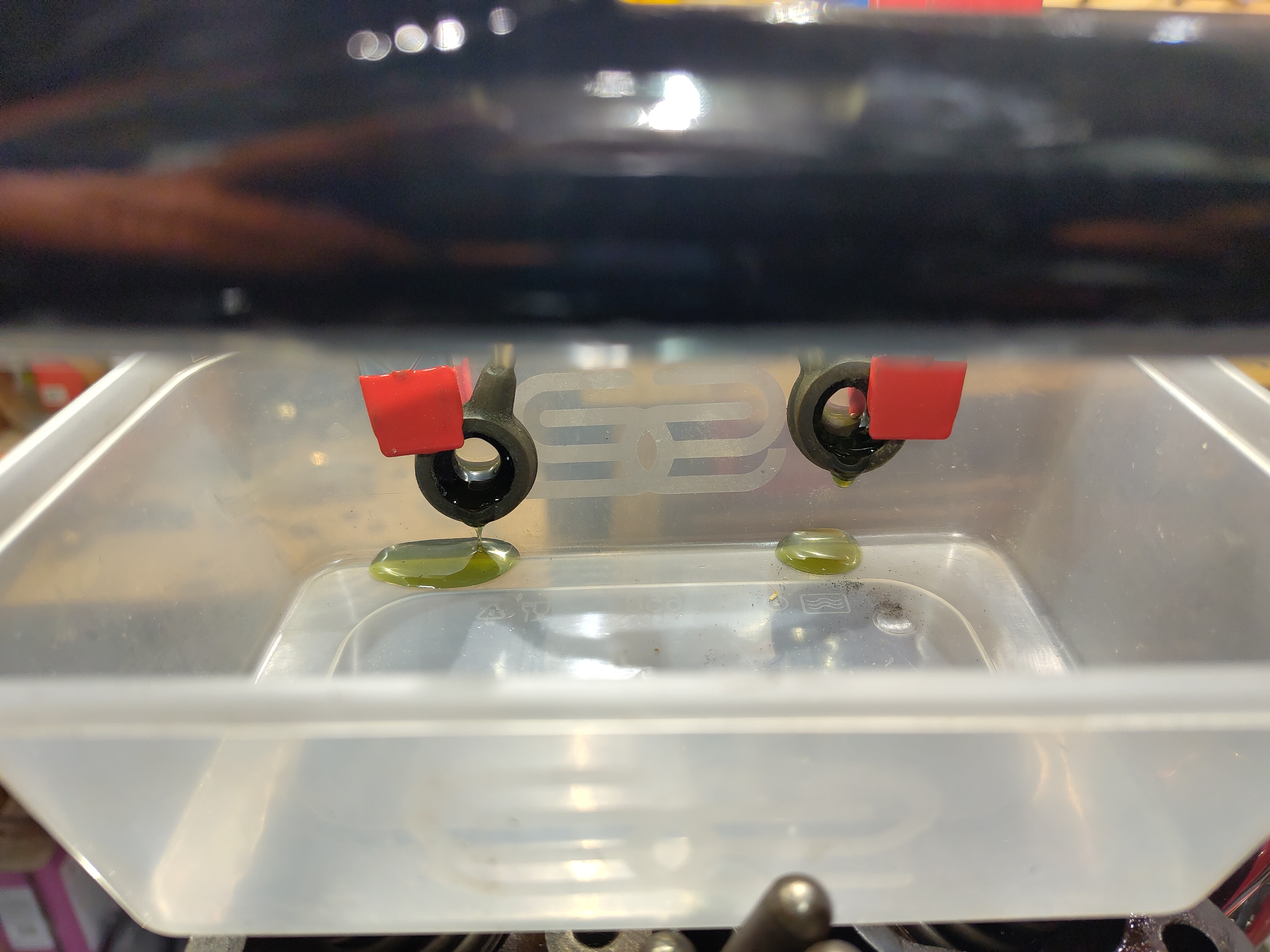
In a post a while back I wrote that given that I couldn't take the horn to pieces to clean the points and that as it worked, I would just go ahead and fit it. The trouble is once I'd wired it up, pressing the button had no effect. It just didn't work. I had it on the bench, checking the resistance of the coil with the multimeter and driving it with a bench top power supply but it was having none of it. It would have to come apart.
The difficulty with these horns is that the armature is retained in the diaphragm by a nut which is extremely tight. It's very difficult to remove, mainly because it's shallow and you have to be careful to hold the diaphragm to avoid it getting damaged. The way I resolved this was to make a wooden clamp that I could put in the big vice and hold the fragile diaphragm against the body of the horn whilst undoing the nut with a closely fitting tube spanner. With a 400 mm tommy bar, which I bent, it eventually came undone.
So that's the horn in bits. Once you've loosened the centre armature nut, you can remove the diaphragm leaving the armature in place. With the diaphragm off, you can slide the armature out from underneath the points assembly and that is about all the dismantling that you will need to do.
The point spring is very strong and it's helpful to use a jewellers screwdriver inserted between the moving point and the fixed point such that you can get a small sliver of wet and dry paper between the contacts to clean them.
Clean all the rust off with the wire wheel and Emery cloth. It's impossible to set the horn up properly if there is still rust on the body and inside the diaphragm and you won't be able to tighten the armature adequately if the nut is still stiff and rusty.
When you reassemble it, if you align these slots in the armature with the peg on the outside of the horn body you will have the armature in the correct relationship with the points assembly. When you have it in the right position you can tighten the nut up again using the same clamping mechanism that you used to undo it.
By the way, that peg is important. You'll note that the diaphragm has an inclined slot which engages with the peg? Well, the diaphragm can be rotated such that the slot causes the diaphragm to move up and down in relation to the body of the horn. This is how the armature air gap is set on these later HF1441 horns. The earlier Altette horns use a big grub screw and a nut on the back of the body for the same purpose. The diaphragm is held in place after setting with a clamping ring around the outside.
The easiest way to test the deflection of the diaphragm is to set the horn up on the bike with a magnetic DTI base sitting on some suitable surface, in this case the pillion footrest mount which on a PRF framed Ariel is quite flat. To test the deflection, back out the horn adjustment screw fully so that the points will not open when the push button is operated. Don't forget to undo the lock nut before you attempt to move the points screw.
When you press the horn button with the screw all the way out, you will hear the diaphragm deflect with a click. If you don't hear anything it's likely that the deflection is insufficient or non-existent so use your hand to increase the deflection of the diaphragm by turning the whole diaphragm anticlockwise slightly.
According to the Lucas instructions the deflection is supposed to be 11 to 13 thousandths of an inch.
When you've got the deflection correct, you can replace the clamping ring to hold the diaphragm in position. Then it's time to adjust the horn points setting: undo the locking ring and adjust the points using a small screwdriver. Turning the screw clockwise opens the points further for each deflection of the diaphragm.
You have to fiddle a bit with this screw to get the tone you want. Don't be afraid to turn it half a turn each way or more if necessary and test the horn each time until you get a tone that's consistent and doesn't sound like a dying parrot. When you fit the tone ring you'll hear it change substantially.
When you're happy with the sound you're getting from your rebuilt horn, don't forget to do up the locking ring, put the tone ring on and do up the acorn nut. I made this tool to turn the locking ring:
This will be the first time that I've wired up an Ariel with the separate instrument panel fitted to the swinging arm frame bikes with the headlamp nacelle. Looking at the wiring diagram it makes sense to wire up the panel separately from the rest of the bike, to be fitted later.
As you've seen, and in line with the wiring diagram, I have fitted a 5-way bullet connector between the main harness and the front end. Some of the cables from the instrument panel will go into this multiple connector, and others will stay on the panel whilst further connections will go into the headlamp.
I made a start on the panel by fitting the ammeter and the light switch. I had the speedometer fitted as well, but found that the speedo lamp fitting was loose in the speedo body and the bulb holder could not be removed so I've sent this off for this to be repaired and the speedo overhauled.
Here's the initial layout. I've put all the wires in and crimped the ring terminals; the next step is to try this on the bike and see where the cable is going to route and how I can tie these cables together in sleeving.
This is the result. You can see I've terminated all the wires now, and added some sleeving and routed some of the wires around the top of the speedometer. I can't do much more until the speedo is back from Russell.
I need to clip the switch in and add the rubber ring around the switch and the ammeter, but it does work and I have both a rear lamp and a stop lamp. For some reason the horn doesn't work?
It's alive!
Next stop on the wiring list is to add the combined horn button and dip switch. This is the original one and I have just removed the old wiring and clean the switch up with degreaser. More of that later.
There's lots of little jobs around the bike to be getting on with. This one is the dynamo cork gasket which I bought from eBay. It was a little big and needed 3/8" taking out of the circumference.
That's the dynamo chain in place. I had one with a split link which I think is unusual - but I think that this is the original chain. I replaced it with an endless one from Draganfly. It's very difficult to tension because whilst you can turn the dynamo to tension the chain, as soon as you do up the clamp it pulls the dynamo back into the crankcase and loosens the chain again...
These are the clamps for the head steady. I've fitted them in place with some leather shim between the clamp and the frame to protect the paint. I'll leave these here for the moment until I have made the new studs for the rock box, and then I can fit the head steadies.
I bought all the cables as universal types from Draganfly. When I unwrapped them I was pleased to find the air and throttle cables were complete with their nipples fixed in place at both ends. Whilst the throttle cable fits ok, the choke inner cable is much too long so I will have to move the nipple.
These two pictures show the routing that I have adopted for the clutch cable. I've shortened the outer to suit this routing, and when the gearbox is back together I will fit the nipple.
I've made up two gaskets for the carburettor and the heat shield.
Perhaps inevitably, the throttle stop is missing from the twist grip. As soon as you slacken the cable these loose stops fall out and can be easily lost. I'll make one on the lathe later - perhaps two, one for the toolbox as a spare.
Edging ever closer towards first start, I diverted myself from wiring activities to time the ignition.
Regular readers will know the rocker box isn't fitted yet, and I can tell you that it's much easier to set the engine in position for ignition timing without pressure from the valve springs trying to restrain you.
As I've fitted 7.25:1 pistons to this machine, I am timing it to Cyclone specification - 3/8" BTDC at maximum advance in place of the 11/32" for the home market models. Here it is on the ubiquitous Wagamama chopstick, of which I have hundreds:
The timing is set with the timing side piston at 3/8" BTDC on the compression stroke.
With the engine in the right position, I fitted my little clamp to hold the ATD at full advance. The ATD is screwed most of the way on, but is not yet on the magneto shaft taper:
With a green Rizla in the points, I can rotate the magneto until the paper just loosens in the points. It's useful to have a 4 BA spanner available to just hold the magneto shaft on that central bolt while you gingerly tighten up the ATD nut from the other side. With the petrol tank off, it's easy to reach the magneto from the timing side of the bike.
Next, fully tighten the ATD nut. You can then back the engine off and come back up to 3/8" BTDC; if the Rizla is just coming loose in the points (with the ATD still clamped to full advance), you are good to go.
Wiring jobs are plodding on at the moment. This next picture shows the splice that I have made to provide a battery feed to the horn and stop switch. It's quite difficult to follow the original wiring diagram and make all of these connections at the battery terminal with modern VRLA batteries with their tiny spade terminals.
It's soldered and covered with heat shrink sleeving.
Here is a view of the rear brake light switch. Behind the oil tank, in front of the mudguard and behind the toolbox is a very difficult position to get to to put that bullet connector in. Ariel clearly assembled the switch and the wiring before the oil tank went on - which reminds me, there is no seat bolt above the oil tank, so the tank will have to come off again!
You can also see in this picture that the rocker feed oil line is not very well fitted to the stub on the oil tank. I pushed this on a lot further.
This next one shows the wiring for the regulator, complete with the seal, clamp and split bullets:
That's the battery area complete. For the record, this is wired negative earth which means I will have to flash the dynamo at some point.
For some reason the battery lids are moulded with four cable access slots. This is because they are a copy of the original moulding which had to accommodate large Bakelite knobs for the battery terminals. I've filled two of these holes with black hot-melt glue.
Next stop, wiring up the dynamo. You can see the dynamo D connection on the left, as it connects directly to one of the brushes. The field F connection on the other side connects to one of the white field cables going into the body of the dynamo.
I oiled that felt before I closed the dynamo up.
That's the dynamo wiring sealed up.
The last job today is to finish the wiring to the rear lamp. These are the finished cables from the harness with Japanese bullet connectors for the stop switch and rear lamp and a crimped and soldered eyelet for the earth.
The earth wire is attached to one of the rear lamp fixing bolts.
I'm not going to blog the complete build of the wiring harness, because I've done that a few times already for the Square and the W/NG. What I will do is show you a few details of the harness as it comes together.
This picture shows the arrangement around the back of the toolbox. From the main harness there are branches going to the horn, to the regulator, to the battery and to the stop switch.
I will probably add a series of bullet connectors to allow me to separate the main harness from the harness going to the rear mudguard.
This next picture shows the main earth cable to the rear which splits into three near the indicators. There is a soldered splice under that heat shrink.
This picture shows the harness going to the rear of the bike with that soldered splice and the wires to the indicators and the rear lamp all covered with PVC sleeving, with a heat shrink section around the joint.
The bike is running an original Lucas 564 which needed to be rewired. I've replaced the cabling and used some heat shrink to provide some wear resistance where the wires go through the rear of the lamp. The connections to the bulb are blobs of solder flattened on the linisher.
Here's the engine earth. This is taken back to the main frame earth which is the upper of the two oil tank bolts. I need to clean the Wellseal off!
For the record this is how I have terminated the magneto kill switch. There is a length of cable, covered in heat shrink, passing through a small length of fuel line which sits neatly inside the thimble nut on the end of the magneto. This end is now weatherproof.
The other end of the magneto cutout cable is soldered into a push button at the handlebar. The joint is hidden by a piece of PVC sleeving pushed over the button - I didn't have any suitable heat shrink to bridge these two sizes.
Today I applied a bit more elbow grease to the ratchet spanner I was using to turn the mainshaft and attempt to get some oil circulating in the engine. I realised that if I put the machine in fourth gear I could achieve the same thing turning from the rear wheel, perhaps with a bit less effort because I'd have the full diameter of the wheel as leverage to turn the engine.
This worked really well and I was able to get the engine moving quite quickly by pulling on the tyre. I persisted with this routine each time I visited the workshop during the day.
Suddenly, it all started to get easier. This happened with the Square Four - the oil reaches the major bearing areas and they start to slide much more freely. I decided to give the big drill another try.
Even turning the wheel I had started to see a lot of oil around the pump. This would be emerging from the cam and idler bearings I think. With more engine speed derived from the drill, this area became a lot wetter but I still wasn't getting anything at the tank.
I was on the verge of giving up for the day and heading home for some tea, when oil appeared at the tank return. It takes a while to get up here when you have a filter, because of course the filter has quite a significant volume to fill:
A couple more minutes on the big drill had oil appearing at the rocker feed banjos.
So that's that - very pleasing. The next step is to close it all up and get it running. Oh, and by the way - this is Morris SAE 30 Running-in Oil. I'll be using Morris SAE 40 generally.
That hasn't been much of a week. My wife and I have both been in bed with the flu, so nothing much has happened on any of my bikes or any other job come to that; I even had to cancel a railway trip this week.
However, the oil tank is hooked up and I started to try and crank over the engine using the gearbox mainshaft nut as an access point. It was quickly shown to me that using a power drill here was not an option, because of course we're driving through the clutch and a primary gear ratio to get to the engine unlike the last time I did this which was directly to the square four front crankshaft.
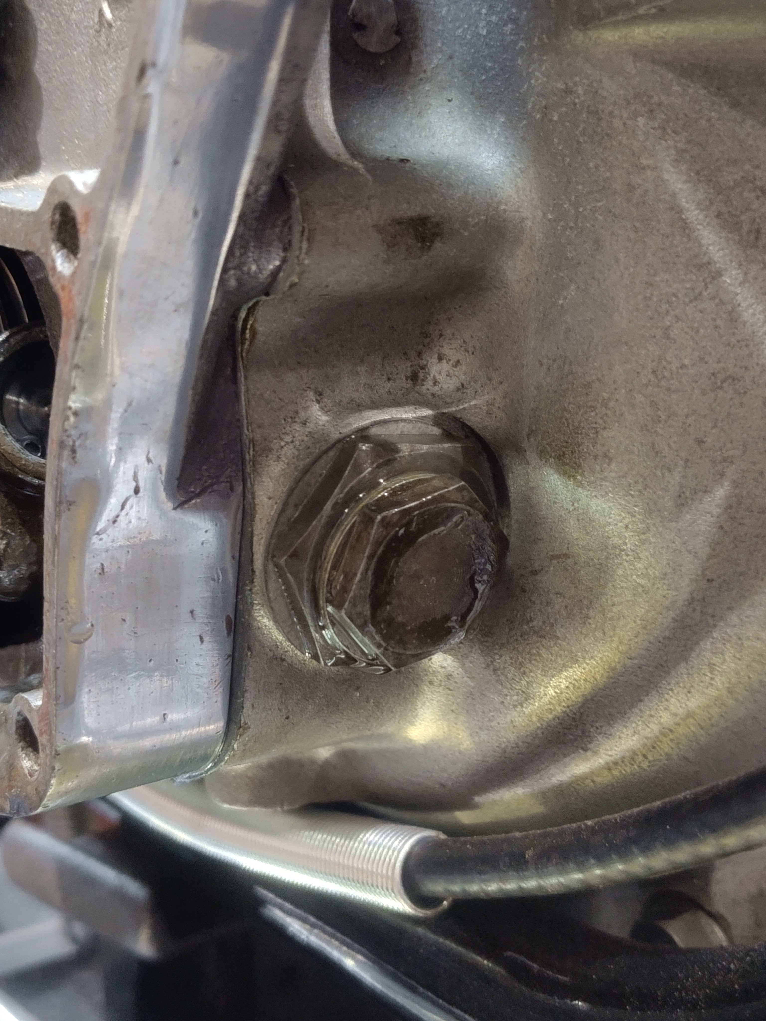
I've been cranking by hand using a half inch ratchet spanner. I've got oil at the relief valve:
I've got oil at the return filter, which proves that the return filter union connections weren't tight enough.
Trouble is I don't have oil at the tank return connection yet, nor at the rocker box banjo connections:
More cranking required. Maybe I’ll roll it down the hill?
It’s amazing what you can do with a few bits of junk lying around the workshop. A leatherwork project (shortening a belt) revealed that sewing leather is not as easy as it looks - even when you have made the holes with your awl, you still need to re-open them as you make each stitch, and I didn’t have a sharp awl.
I had a long, sharp needle of about 2 mm, and went in search of a file handle - all of which had file-tang size holes in them, when the little wood lathe caught my eye. I sliced a bit of scrap oak on the bandsaw to make a 1” square blank, and attacked it with chisels:
I turned the end to 13 mm OD, to fit snugly inside a bit of 15 mm copper tube; I annealed the tube and formed the end over so that I had a neat ferrule, and glued it on the handle with some Loctite, pushing the needle into a 1.5 mm hole in the end.
A bit of a boring post, but I just need to catch up with where I am. I have four work faces with various bits on order and I’ll summarise where I am in order to work out what to do next:
Engine: waiting to fit the rocker box and the ATD. I need a couple of replacement studs for the rocker box/head/head steady connection which I’ll make on the lathe. I’ll spin the engine to get the oil circulating before fitting the rocker box, and I’ll fit the ATD when the rocker box is fitted.
Oil System: waiting to finish the connection of the chain oiler and rocker box pipes, and clean the oil tank, before finally fixing the oil tank in place. I’ve ordered the running in oil and the SAE 40 for later. I’ll need to put a cupful in the sump (probably through the rocker box drains) and to fill the return filter through the hose.
Gearbox: I’ve made the new pushrod from 5/16” silver steel; I have the gasket and the ball; I’m going to spin the engine on the mainshaft nut to get the oil system working and once I have done that I can fill the gearbox and put the kickstart case cover back on.
Clutch: waiting for the gearbox to go back together for testing. May need new corks, which are in stock.
Chains: primary is in, tensioned but not oiled; secondary has a dummy fitted.
Exhausts: waiting for the clutch dome and timing covers to go on.
Electrics: I’ve reviewed the wiring diagram, estimated the cable lengths and ordered the cables, bullets, straps and sleeving. The dynamo is not connected up yet (mechanically or electrically), but it works.
Control Cables: There’s nothing stopping me making the cables for the carburetter, though the clutch cable needs to wait for the gearbox case to go back together.
Wheels & tyres: these are parked until the machine is running.
As you know I have a diverse range of interests, though they are often linked in some way. When the Model A finally finds a space on the bench, it's going to need a seat cover and two leather 'front's' for the toolboxes, so I have a hankering to learn about leather working. I've also made one or two knives...
Leatherworking is one of many hobbies for which you can buy a huge range of tools with an equally huge range of qualities. I'm a beginner, unwilling to invest in something I may be no good at, and unsure of what tools are really useful. My wife bought a few old leatherworking awls, which I cleaned and sharpened, with a view to trimming an over-long belt that I have had for years, from the buckle end..
Remanufacturing the belt with the buckle in a different place involved slimming down the end of the belt to reduce the thickness of the leather - a process known as skiving.
Skiving is used in leatherwork especially in areas that are to be bent or folded and which must be pliable without becoming weakened. You really need a wide bladed knife for skiving; there are plenty of cheap ones available on eBay but of course you get what you pay for and they are unlikely to be made of decent steel. As you know I've made a few knives and it was a simple matter to make one of my own from a piece of 40 mm wide 1095 knife steel.
As usual I drew out the pattern on a piece of paper stuck to the steel. This is 3 mm thick flat bar to provide a stiff and heavy knife. The profile was cut out with the hacksaw and filed to shape.
I cut the primary bevel on the linisher before heating the blade area cherry red in the furnace and the quenching in oil.
Whilst the blade has yet to be tempered it takes an edge very well and it's perfectly suited to the job it was designed for.