Saturday, 29 June 2019

Pillar Drill

I've had a small pillar drill for about a year, and pretty cr@p it is too - but it was very cheap and it's a whole lot better than what I had before, which was a hand-held power drill in one of those bench stands.

This one works well enough, it has the usual stack of five pulleys and belt drive, belt tensioner, convenient power switch etc and you can set the table at an angle. But it is very flexible - the base and the table are pressed steel and the pillar is very thin - the whole thing will bend when you put any feed on.

The spindle is mounted in sealed bearings but once the quill descends it has quite a lot of play.


Here's the depth gauge and guard - this is hard plastic and broke almost the first time I used it. The depth gauge requires you to fiddle with those two nuts:


I decided to make a new mounting for the guard and depth gauge, but mostly because I want to do some boring in a big-end type arrangement (like a locomotive eccentric strap). The new mounting is made from two lengths of 10 x 30 mm aluminium bar, screwed together with two M4 screws and shaped to match the old one. Here, I am aligning the components with the lathe centre prior to drilling and boring a 40 mm hole to suit the journal on the pillar drill. The two halves of the clamp are spaced 1 mm apart, so they clamp securely to the drill:


Here it is in place, along with the broken bits of the original:


Thursday, 27 June 2019

Mini Lathe Updates

Readers might be interested to know that the mini-lathe page:

https://ariel-square-four.blogspot.com/p/mini-lathe.html

has been updated this week, with a few new bits:
  • a 3D printed apron gear cover
  • a modification to the tailstock die holder
Thanks for reading, and I hope you find it useful.


Dry Build - Siting the Oil Filter

These plain journal engines run close tolerances and need a decent oil filter. Modern oils keep the dirt in suspension and if there is no filter, the oil becomes contaminated very quickly.

The SQ4 has a Norton commando oil filter, like this one, fitted under the gearbox where:
  1. you can't see it
  2. you can get to it easily
  3. it doesn't ground on kerbs
We'll need a similar site for the filter on the FH.

There's a lot of space behind the engine, between the engine/gearbox plates - but not for this filter, which is marginally too big for this location.


Beneath the swinging arm and in front of the mudguard is a likely location used by many FH owners. I'll need to find a location where I can easily mount the filter and where the oil lines will be able to get to and from it without kinks - and it must also fulfil the other criteria I listed above.


This is probably no good - there is nowhere to mount to and the oil line routing could be a bit tortuous:


This is an example of a mounting used in that area:


This one is on AOMCC forum member Steve Carter's Ariel Cyclone.

And another - this is AOMCC Kieth Mettam's filter:


Another one from Steve Carter, this well used Huntmaster carries a Morgo filter - these are smaller than the Commando filters and easy to place - but they are quite expensive and it makes sense to me to use a unit I already have elements for, commonality of spares and all that:


This is my choice. I'm using a mock-up bracket, made from a bit of 20 swg sheet, welded to an old footrest bar sleeve nut and placed in the sidecar lug beneath the swinging arm:


It's too far back, and the oil lines foul the gearbox casing:


Time to cut it up and shift it around:


To become this ugly but effective thing, including a bit of butt welding practice:


Also pictured is the beginning of a special bolt that will locate the filter bracket in the sidecar mount.


This is better. It's further inboard to allow the oil lines to pass the gearbox outer casing, and further forward to guarantee the filter clears the mudguard and rear wheel:


The next step is to replace the bracket with one made from 3-4 mm sheet, and finish the special bolt that holds it in place. I'll use the same old sleeve nut, but I will probably machine a journal in it to fit in the hole properly.

Here's the finished bolt:


It's in the wrong side, but I'm just testing for fit. I wanted to make it look like the swinging arm nuts.

I'm tubing up using a mixture of Huntmaster and BSA A10 oil lines. The long A10 lines stretch from the engine right around under the gearbox to the oil filter:


I've spent a long time faffing around with these connections, even considering moving the filter altogether. In the end, after a session mulling it over one night in the workshop with my son, we concluded we could get it all in there if we modified the fittings:


I've shortened the unions in the lathe and gained about 5/16" which is enough to give the gearbox it's full range of adjustment. This allows the gearbox to move and the oil lines to follow the routes I'd laid out. A minor problem is that the return to the tank is touch on the long side and the route has to cover a 120° bend on top of the gearbox, which is a bit unsightly.


Final filter bracket:


Tuesday, 18 June 2019

Brown Trouser Moment

I've had a few nervous moments in SQ4 ownership, shared by several co-owners if the stories on the AOMCC forum are anything to go by. Not least of these are the few occasions where oil pressure has suddenly and completely disappeared, accompanied by a more or less continuous return flow to the oil tank.

Fortunately, the first time this happened was on start up - or at least, that's when I noticed it. Investigation was interesting - removing the front main bearing cover to look at the oil pressure relief valve revealed that the spring had become caught in the split pin, and the split pin was now part way down the spring, preventing the spring exerting any pressure on the ball and allowing it to come off it's seat.

I put it back, noting that the direction the spring was wound in would always allow that to happen and wondered if original springs are wound in the opposite direction.

It happened twice more - once outside a smoke house along the coast. Knowing what it was, it was any easy fix if a little nerve racking - everything was rather hot, and I was nervous of losing small parts in the dirt. However, I was buoyed up by another motorcyclist stopping to see if I was OK.

The next morning, the same thing happened - very low, but not zero, oil pressure on start up. It had happened again.

I needed to do something. The spring lives in a bore which is a little over 6 mm - I can't measure it, but a 6 mm drill is a rattle fit while a 1/4" drill won't go in. The spring is about 5.5 mm OD and 4.5 mm ID:


I planned to make a brass cap to house the end of the spring, preventing the split pin from coming into contact with the coils.

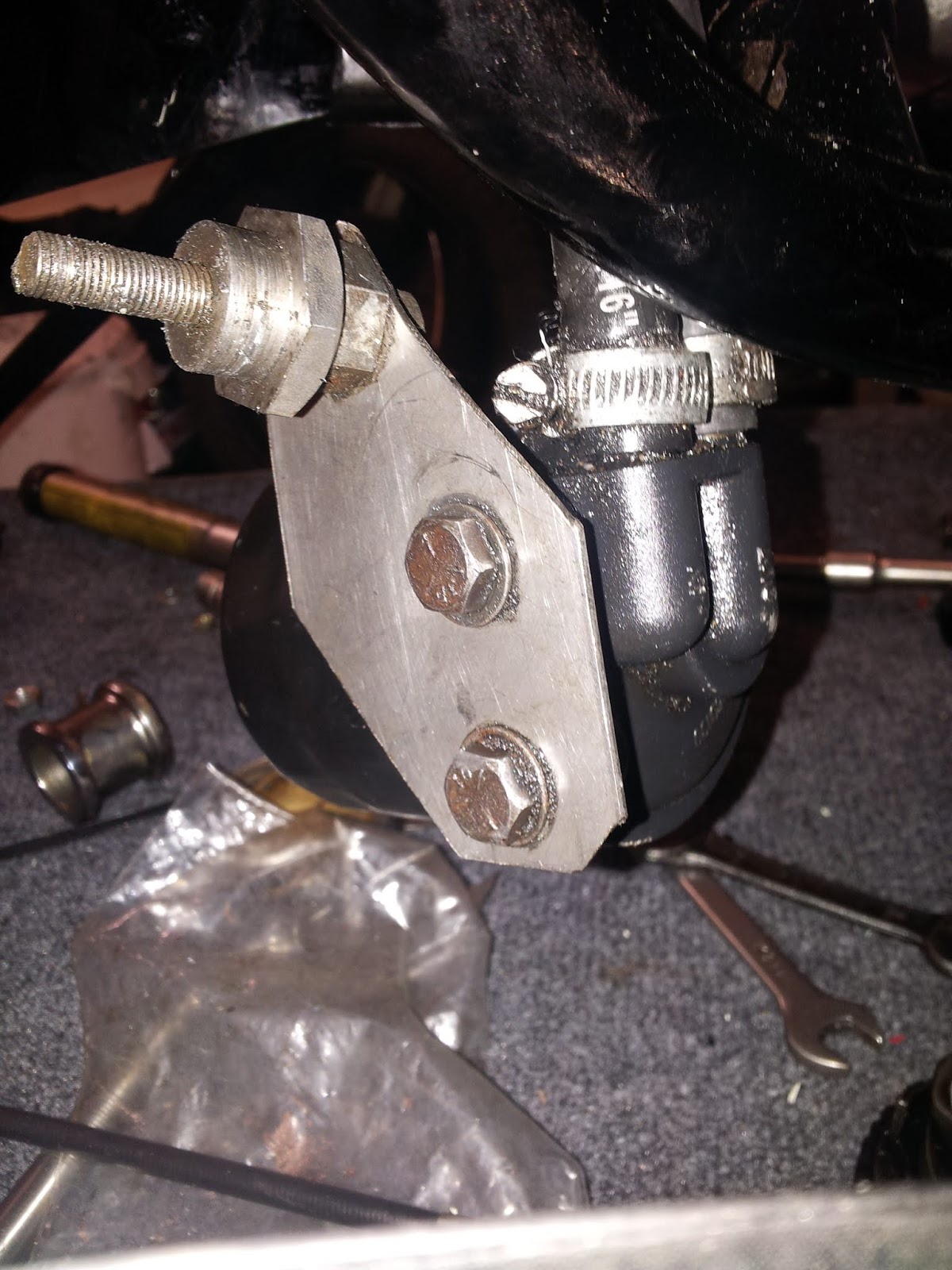
However, I came across this cable ferrule which fitted beautifully. all I have done with it is to drill it out to 3.5 and use a needle file to open it a little more - all the relieved oil has to pass through this hole:


This works perfectly, and makes it much easier to get the split pin in.

Monday, 20 May 2019

Dry Build - Fitting the Swinging Arm

Next, it's time to fit the swinging arm and understand how the FERC fits around it.

At first, I struggled to get it in at all. It's difficult because the frame tubes behind the swinging arm mount are more narrow than the width of the swinging arm...


The secret is to lift the frame at the rear, drop the swinging arm and come at it from underneath, with the swinging arm cocked over so the offside is higher than the nearside. Once you get the nearside more or less adjacent to the nearside mount, the offside will rotate up into place. This works because there is more space in front of the offside swing arm mount - the gearbox interrupts the nearside.


I made a decision about the bushes - Steve Carter, marathon FH rider from the AOMCC changed his rubber bushes for a pair of oilite bushes and a much larger swinging arm spindle, and I am going to replicate that approach. Those bushes have a reputation for being a bit of a pig to remove. I thought I would try a hole saw, between the two metal tubes and sawing only through the rubber. It worked fine, with a bit of silicone grease to prevent burning but ultimately my saw was too short:


I resorted to the more traditional approach - a twist drill:


This works very well and of course if sufficiently long will cut all the way along the length of the bush:


The next job of course is to remove the outer sleeves from those 'SilentBloc' bushes. Easier said than done.

My first thought was to weld a plate across the sleeve and drive the whole lot out. I got a decent weld, and then proceed to drift it out - and tore the weld out with the plate attached. The sleeve stayed in the swinging arm.


The Dremel is a more traditional approach and works a treat. I cut a slot in one with a burr; the burr was ruined, but cut one slot before it passed away.


Once you have the slot cut, you can prise the sleeve out of contact and it will be loose enough to drift out.


First battle won.


Tuesday, 30 April 2019

From the Archives

Pathé News was a producer of newsreels and documentaries from 1910 until 1970 in the United Kingdom. Its founder, Charles Pathé, was a pioneer of moving pictures in the silent era.

Its roots lie in Paris when in 1896 Société Pathé Frères was founded by Charles Pathé and his brothers, who pioneered the development of the moving image. Charles Pathé adopted the national emblem of France, the cockerel, as the trademark for his company. After the company, now called Compagnie Générale des Éstablissements Pathé Frère Phonographes & Cinématographes, invented the cinema newsreel with Pathé-Journal, French Pathé began its newsreel in 1908 and opened a newsreel office in London's Wardour Street in 1910. Wardour Street, in Soho, was to become a centre of Britain's film industry. In 1958, Pathé was sold to Warner Bros. and became Warner-Pathé. Pathé eventually stopped producing the cinema newsreel in February 1970; by that time, many homes had their own or rented televisions and the days of the cinema news reel were over.

The Pathé News archive is known today as British Pathé. Its collection of news film and movies is fully digitised and available online and it's no surprise that that archive includes film of our favourite subject. You can do a search like this:

https://www.britishpathe.com/search/query/motorcycles

This famous film of Harry Perrey crossing the English Channel on a 1929 'Black' Ariel was made by Pathé and is here too:

https://www.youtube.com/watch?v=Wmbc3QSSyqA&feature=youtu.be

Harry was Competitions Manager at Ariel until 1930 and apparently, on arriving in France after a 7 hour trip, Perrey returned to dear old Blighty, on his Ariel, the same day!

In 2019, 90 years later AOMCC President Ariel Atzori will repeat the experience though in slightly warmer climes, on Lake Como during the 2019 Italian Ariel Rally.

Monday, 22 April 2019

Dry Build - Rear Brake Pedal & Bell Crank

Updated: first published 15th January 2019

Let's have a look at the brake pedal and crank arrangement next. Here's the crank in place - the rod is very rusty & I broke it trying to dismantle it...


The crank is held in place with a hex head screw (which I think is 5/16" CEI) and a large washer - both of which are missing. There's a clevis on the end of the brake cable.


I'd thought I might buy a new rod assembly from Acme, but having attacked the original with the wire wheel I see that much of it (rod aside) is in pretty good shape and would replate, so I have sat the broken bits in the vice with some Plus-Gas in them.


Drilling that broken rod out is going to be straightforward. Here's how I did it:


I decided to use the lathe to ensure that I drilled the broken std out on-centre. Since it was tricky to hold the banjo shaped swivel in the chuck, I made a simple collet out of a bit of aluminium round bar. The larger part of the swivel would sit behind the collet, which grips the parallel part.


I used the collet to hold the swivel in the 3 jaw chuck, and drilled the bit of broken rod out with progressively larger drills. I cleaned up the thread with a tap.


The rest of it cleaned up easily with the wire wheel. The bolt and washer used to retain the bell crank in the frame are missing - I understand (thanks to Mick D on the AOMCC Forum) that the bolt is 5/16" CEI, about 3/8" long. The thread needs cleaning up:


I've turned up a new washer from a bit of 25 mm 303 round bar:


Moving on, the brake pedal is all good and the spindle fits nicely into it's hole in the frame.


No idea why it is plated though. The spring, although it fits and is working, is very pitted and will need replacement:


I've made a new brake rod from a piece of 1/4" round bar. The collet chuck and tailstock die holder are very useful for jobs like this:


Here we go, new and old:


All fitted up. Next step is a new brake pedal spring and then the brake light switch.


Update:

The brake light switch fits onto a welded bracket on the frame down tube, right above the swinging arm, close to the abutment for the brake cable:


The brake cable uses a clevis arrangement to connect to the bell crank. This one is a bit long, and needs a washer and a split pin:


Tuesday, 16 April 2019

Barrels & Pistons

Let's have a look at the barrels and pistons again. some time back we had a preliminary look, but since everything is apart now we can make a more thorough examination and dimensional survey.


Armed with a bore gauge and a micrometer, we can do some measurements:

Parameter
Transverse = parallel to crankshaft axis
Longitudinal = parallel to motorcycle axis
Dim’n
Wear
Data Source
Position
Number 1 – Drive side
Number 2 – Timing Side
Number 1
Number 2
Cylinder Bore upper transverse
¼” down from gasket face


2.821”
2.819”
Cylinder Bore upper longitudinal (A)
¼” down from gasket face
2.817”
2.817”
Cylinder Bore middle transverse
1” down from gasket face
2.816”
2.815”
Cylinder Bore middle longitudinal (B)
1” down from gasket face
2.813”
2.815”
Cylinder Bore lower transverse
2” down from gasket face
2.816”
2.816”
Cylinder Bore lower longitudinal (C)
2” down from gasket face
2.811”
2.813”
Piston (ring land area longitudinal) (A1)


2.793”
2.792”
Piston (ring land area clearance) (A-A1)


0.024”
0.025”
Piston (below rings longitudinal) (B1)


2.811”
2.812”
Piston (below rings clearance) (B-B1)

0.002”
0.004”
BSA Service Sheet 216
0.002”
0.003”
Piston (Extreme Skirt longitudinal) (C1)


2.813”
2.813”
Piston (Extreme Skirt clearance) (C-C1)

0.002”
0.004”
BSA Service Sheet 216
-0.002”
0.000”


All the rings were stuck so the pistons are away for a well earned soak in the parts washer. I'll leave this picture here so I don't forget where they are: