Monday 11 December 2017

Power to Weight Data

I've been meaning to look at power to weight ratios for a while, mainly since the PO of my SQ4 delivered it to me saying 'I can't see myself using this, it's a big bike and way too heavy for me'. I thought I would look around at some modern bikes and see how heavy it really was, and whether I was going to be able to ride it into old age.

So the table shown here lists a few bikes of interest to me, with their fuelled-up weight in pounds, seat heights for some and power to weight ratios. Look at some of the older bikes & how they compare with some newer ones!


Here's the power to weight ratios charted. enjoy figuring that out, I will replace the chart with one that is easier to read!

Wednesday 6 December 2017

Imposter

Know what this is, my fellow Ariel-junkies?


This is a Triumph 3HW. Know what carburetter that is? It's a Amal 276AD/1J. Why am I telling you this? Look at this picture:


Yes folks, that is also an Amal 276AD/1J, fitted where my Ariel's 275B/1J should be. This is interesting, because this is the carburetter my bike came to me with, and it is jetted (120) as the 275 would have been; the larger 276 would have used a 150 - to match its 1" choke (the original W/NG carburetter would have been 7/8"). No doubt this came from another of the thousands of military bikes floating around in Italy, or some ARAR compound when my bike's original 275 was pinched or wore out - or maybe it was changed by the Army whilst the machine was in service. We'll see what cutaway & needle jet it has when we get it apart.

Tuesday 5 December 2017

Carburetter Rebuild

Regular readers will know that there have been a few challenges around the carburetter recently, and that I've started poking around in it.

The first sign of trouble was on the overrun, heading downhill into town with what felt like fuel starvation. A couple of days before, I had run out of petrol on the SQ4, through my own fault (the SQ4 has no reserve tap, a long story) so I was congratulating myself for my inattention again. Pulling on the reserve tap made no difference and limping to my destination saw the tools out and a chunk of debris removed from the main jet. I went home with the jubilation that only a roadside repair can provide.

I started wondering why the bike was quite so slow. Investigating the carburetter slide revealed it wasn't opening fully as previously reported:


The investigation also revealed an uncomfortable tendency for the slide to stick caused by a non-standard throttle return spring, something that showed up in the shop but not thankfully on the road. The carburetter would need some investigation soon.

And remember that blocked jet? That came back to haunt me while coasting downhill into a village near here, when everything started popping and banging, spitting neat fuel back out the carburetter. I limped along for a while with a wet knee, eight-stroking (I thought only Bantams did that?) eventually realising that going home was not really an option, because after all what would I have done if I had been hundreds of miles away?

Pulling the tool roll out, I took the Amal carburetter spanner and removed the jet cover or 'Float Chamber Holding Bolt' to check the main jet - which wasn't there. It was sitting, loose, in a puddle in the bottom of the jet cover.

Perhaps someone didn't tighten it properly? And while you're at it, that fuel leak you have been complaining about, that you thought was the float valve not sealing? Perhaps you ought to tighten the big nut on the bottom of the mixing chamber?

So anyway, the carburetter is back together, not leaking and the bike is running happily with the needle in the right notch. However, we definitely need a new throttle spring, so we better get on to Burlen Services. Investigation of their website reveals there is a short spring and a long spring, but which one?

Tuesday 28 November 2017

A little maintenance

The W/NG, since I'm shaking down and it is at the front of the garage, is my go-to bike at the minute. Since I made this list I've done a few jobs:
  1. Grease the forks & replace the missing nipple - done
  2. Maybe replace the fork bushes - not done
  3. Tighten the brake torque arm anchor or weld it in - done
  4. Make a T-bolt for the exhaust clamp - done
  5. Adjust and lubricate the primary chain - done
  6. Have a look at the clutch - not done
  7. Change the regulator to a V-Reg - done
  8. Fit a couple of transfers - done one...
I had a nice little trip out a couple of days ago to test the exhaust, which was great but the bike is not very fast and I'm not satisfied that I've got it running as well as it could.


I noticed that the carburetter slide was not reaching full travel for some reason, and that the plug was pretty dark. It's also had a bit of an oil leak from the inlet rocker shaft, which as you can see has heavy flat washers fitted over the banjos and the fibre washers. Not surprisingly, the oil leaks down the threads and comes out under the nut.


So what to do? What we always do in these situations - ask an expert, which always means someone in the AOMCC. In this case, a post to the forum yielded lots of useful information including this from Paul Jameson:

The correct assembly is as follows:
  1. Slacken off the screw on the opposite end of the rocker shaft from the banjo.
  2. Fit copper washer, then banjo then copper washer then acorn nut.
  3. Tighten acorn nut.
  4. Tighten screw on the opposite end of the rocker shaft from the banjo.
And this is why. Paul Jameson again:

The rocker shaft has a shoulder which goes against the inside of the rocker box so with the method above you tighten the nut, banjo and washers against the shoulder. The rocker shaft is sealed so that oil cannot emerge under pressure at the screw end. Hence the screw only seals against oil running along the outside of the rocker shaft.

So, undo this screw on the opposite side:


And you can see the end of the rocker shaft. Grip this with a very large screwdriver or a washer in the slot, and tighten down the acorn nut on the other end, against the fibre washers, then replace the large screw and snug it down into the milled recess to seal the rocker box.


Next, have a look up the inlet tract with the throttle fully open. Yes, I know I can see the carb slide:


Something odd here!

Let's have a look at the slide and spring. First off, the needle shouldn't be in that position, which is why my plug is sooty - it should be in the middle slot; secondly, that doesn't look like an Amal spring and fiddling around with it allows the slide to move up fully. Shame it doesn't return properly... It looks like it has its original brass slides though.


We'll have to get a new spring at least.

Turning to the back end, the chain has loosened off a lot. The primary chain is fine, and the chain is easily tightened up using Ariel's handy adjusters; odd spanner size though, the hex appears to be 3BA.


So that is that for today - we need a couple of seals for the rocker shafts, a new carburettor slide return spring and some front wheel bearings for the SQ4.

Thursday 23 November 2017

Exhausted by all the noise

Blatting about North Norfolk I've become aware of quite how loud the W/NG is, partly due to its original silencer and partly due to the poor fit of the exhaust pipe, which is well and truly battered, to the cylinder head.

I've no intention of doing anything about the silencer, or the battered nature of the pipe since they are irreplaceable original parts, but I must fix the joint to the head as it is leaking fire and smoke with every other piston stroke. You might recall I made a new exhaust pipe clamp which has done well but it cannot deal with the fact that the pipe does not fit...


I looked at various ready made mild steel exhaust pipe bends available at a well known internet auction site, before I twigged that I had an old exhaust header in the loft, the perfect diameter:


And the perfect shape:


I cleaned it ferociously with emery tape:


I need about 45 mm of this tube to reach the head, using the full length of the cast stub. The exhaust has had a repair in the past which was not aligned correctly, leading to the leakage problem, but leaving 5 mm of this old repair piece in place means I do not have to weld to 75 year old steel.


I've put a ring of masking tape around the old & new tubes, to show where I have to cut and to keep the cut square.


Clean the inside:


I've marked the outside of the bend with a Sharpie to make sure the pieces are aligned as I go to tack up.:


Now tacked in about 6 places, we go to trial fit. Not too bad the first time, but ideally needs more angle - I needed to cut a wedge out, to bring it closer to the head at the top.


Now fully welded & a first coat of paint applied:


Clamp added:


Just got to finish painting it now.


Sunday 19 November 2017

Sunny Autumn Day 2

Cley village this time, along the North Norfolk Coast & back by a round about route. The W/NG is the machine of choice at the moment, partly because it needs shaking down and partly because it is so good at these roads - but also because it is at the front of the garage.

Here she is at Cley Church:


Shes starting and running quite well at the minute, though I'm really not convinced the ignition timing is correct and the exhaust to head joint is leaking. This needs a proper repair, as the straight piece of pipe welded on by PO is at the wrong angle and hasn't a hope in hell of making a gas tight seal...


I have a suitable bit of pipe in the loft, from an old SQ4 Two-into-One. It got the right sort of curve:


More later. Hopefully this week, though I am loath to take it off the road

Wednesday 25 October 2017

Lights - not so fixed

Well the W/NG had a nice little trip along the coast to Cromer with its new double dipper LED headlamp, supposedly adjusted for focus and in the W/NGs shiny new reflector. Here it is, waiting to go home again:


The trip home was a lot less fun than the trip out, mainly because it started to rain, but also because the horrible BPF 'contact holder' decided to let go of the dip beam contact - fortunately main beam was still good, and whipping off the reflector by the roadside - no tools required, we have a nifty spring clip:
Secondly, despite the new reflector and 'supposedly' adjusted focus, the beam was really no better. In fact, the halo around the trees close to me was a lot worse - the bulb performs better in the old 700 reflector fitted to the SQ4, suggesting that the Indian reflector fitted to the W/NG is poorly designed or perhaps that I made matters worse by moving the BPF flange on the LED.

Here's the main beam with the LED:


Anyhow, the old 35/35W halogen is back in the W/NG and looks like this. Dip beam:


And main beam, showing better focus than the LED:


I'll check it out on the road later.

One more thing - I noticed that the speedo bulb was a bit dim. Pulling it out, it had '12V' faintly marked on the case... No wonder it was dim on the W/NG's 6V system!

Sunday 22 October 2017

Lights fixed...

After a trip out on the SQ4 recently, I realised that some improvements to the lighting would be helpful. The SQ4 has a LED headlamp from CDRC - one of their 'double dipper' lamps in an old BPF reflector. Dip is very good, and high beam goes a long way but doesn't illuminate much when it gets there...

Looking at this lamp against a tungsten BPF bulb I have realised the it needs a little focus adjustment (its quite old - later ones are apparently adjustable) and axially it does not align properly.

I've de-soldered and moved the mounting ring to fix both the alignment & focus problem, but to sort the reflector out I have put it in the W/NG, which has a relatively new reflector.

We'll need a night time test run to see how we get on, and where we go with the SQ4. In the meantime, the W/NG also has a new dip switch:


Only problem is, the dipswitch is too close to the ignition lever on full advance...

Wednesday 11 October 2017

A few little updates

So, a two weeks is a long time with no blog posts, but I have been out and about and done some of the little jobs. as you will have seen, I've updated the regulator and all is working fine now. Unfortunately a 20 mile road test a few days ago revealed that all was not well with the old Italian dip switch that came with the bike, in that it appears to have several extra positions, most of which give no light at all. More on that later.

Still, the bike is going well. I have several old, original grease nipples courtesy of that nice Mr. John Mitchell of the AOMCC, and these have allowed the girders to be greased properly:


The girders are now bobbing up and down with every little ripple in the road. Secondly I've cut a screwdriver slot in the brake torque arm anchor to help me tighten it up:


This modification was inspired by the W/NG that lives at the Norfolk Motorcycle Museum, in North Walsham:


I've also had a look at the primary chain, which I found was tight at certain positions. I've backed that off a little and added some SAE 50 to the chaincase - everything sounds happier in that direction now.

Friday 29 September 2017

Updating the Lucas MCR1 Voltage Regulator

The little Lucas MCR1 is used with the short Lucas E3 dynamos, like the one fitted to my W/NG.

I like my bikes to look period, but I don't mind updating them to improve performance if there's no visible sign of it externally. The MCR1 was not working, and since I have a similar electronic regulator on my SQ4, which has been looking after my charging system for years, I have no qualms about updating this one.

The update to the SQ4's MCR2 Regulator is shown in a previous post. Today we are looking at the MCR1.

I am going to fit a modern V-Reg 2b dynamo regulator which is designed to replace the mechanical regulator with modern, reliable semiconductors, can handle up to 100W at 6V and even more for the 12V version provided the dynamo is capable of delivering this power. This device is proven and reliable and is available in Positive or Negative earth. 

New features of the 2b include: 
  • Current limit to the field winding, allows excellent performance when using a 6V dynamo on a 12V system while not straining the dynamo. 
  • Tougher electronics, with the introduction of higher energy spark suppression to reduce spikes generated by the dynamo. Improved "thermal foldback" which progressively reduces output power if the regulator gets too hot, indirectly limiting the dynamo from excessive current. 
  • Better servo loop stability, with new electronics which 'predict' when the output voltage is nearly correct and control the field current earlier.
Mine came from AOServices, who manufacture the V-Reg. You can buy them from a number of other suppliers, but Alan Osborn at AO provides a fine customer support service here in Norfolk. when you order your regulator, you must specify the polarity - a positive earth regulator uses different components to a negative earth regulator, and yo cannot convert them. However, the same V-Reg 2b will run a 6V system or by cutting a simple wire link will run a 12V system.

Here it is, with the original 1942 MCR1 quaking in the background. That little green wire is the 6V/12V link.


To get inside, undo the wire clip and remove the cover to reveal the coils & terminals. We'll be removing those coils in a moment:


Here's the underside, showing the two screws holding the bobbins in place:


The cover is stamped with the month and year of manufacture:


Now to start work. The original D terminal screw is soldered in place - peel the solder away and remove both of the visible screws:


The coils will now be loose. Cut all the wires to each of the terminals, being careful not to damage the terminals:


Lift the coils away:


Remove the clip. It's going to get in the way:


Clean up thoroughly. This is a glass brush - it's quite abrasive and does a fine job of cleaning the terminals and the muck around them. Clean the rest down with a spirit wipe.


Take a small soldering iron (this one is a variable 60W iron) and remove the solder and any remaining strands of original wire from the terminals. You can use a solder sucker if you need to.


Then clean the terminals with your glass brush or a sharp knife. Make sure the holes are clear.


Cut off the eye underneath the regulator. It's connected to the D terminal - you don't want charging voltage escaping into the rain. It easier to do this from above, unlike my picture:


Now, the MCR1 is a lot smaller than the MCR2 we upgraded for the SQ4, and the mounting for the V-Reg 2 needs to change. Here I'm using four adhesive pads to stick the V-Reg to the Tufnol insulated base of the MCR1. Don't stick them down yet.


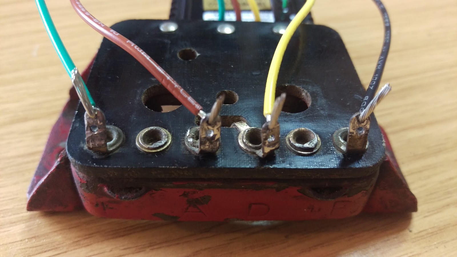
So here we have bared the wires and carefully threaded them through the holes in the correct terminals. BE CAREFUL! you don't want to get this wrong and destroy your new regulator. Bend the bare ends to align with the terminal and increase the strength of the joint.


Now solder the wires in place. Make sure you have heated the terminal effectively, so the solder flows cleanly and wicks into the conductor strands. Don't melt the solder directly with the iron, but let the work heat the solder - that way, you know the wire or terminal is hot enough to make a good joint. I'm using electricians cored solder here:


Coil the wires above the regulator such that they stay within the MCR1 cover, and retain with a small tie-wrap. We don't want to introduce a fatigue failure or have these wires trapped somewhere.


All done:


Finished, with no visible changes:


And the bike is charging: