
I like challenges - not ones where you have to swim a few miles (or even metres) in freezing cold water or ones involving dancing or some other difficult limb - coordination activity, but ones where I can see myself achieving the goal through a bit of application, like climbing a mountain.
Here's one - emulating the fuel and oil caps on the QR. I don't want to buy the bits - it would be too easy just to turn this into a cheque book rebuild, but I can use the tools and materials I have knocking about or cheaply available to make a functional and visually passable copy of the part I need.
You will have seen the oil cap post and maybe the fuel cap post - both of these are turned from Acetal but have features allowing the hand an easy grip. These features can be milled but to look good will need accurate positioning and that needs the work to be rotated in a controlled way such that the milling cutter can machine regular slots in the circumference of the part.

The way we will do that is to use a rotary table to hold and move the component a set fraction of a turn for each cut. Here it is - it's a 3" rotary table from RGD Tools.

I'm going to hold the work in a chuck - the three or four jaw, or maybe a smaller 3" chuck if I think I can use the space. In any event, we will need a plate to bolt the chuck to the table - an adapter plate. This is necessary because the rotary table has three T slots and the chucks have three or four M8 stud fixings.
I plan to make this adapter from this chunk of hot rolled (black) mild steel that I bought on eBay. In retrospect, this was a mistake - I probably spent more on replacement tool tips than I saved on the hot rolled steel. It has hard spots which are quite capable of wearing out HSS lathe tools or chipping carbide tools.
I didn't know that at the time.

Anyway, I marked the centre and faced it in the four jaw chuck.

I chopped the corners off in the disc cutter when I realised how difficult the material was to machine, which made it a bit easier to machine the register for the chuck. The rotary table has a 5 mm centre hole which I have drilled and reamed in the adapter:

The register is turned a few thou' undersize and fits the back of the chuck beautifully:

While it was still on the lathe, I marked the PCDs of the bolt holes:

I set the adapter up on the rotary table to drill the first bolt hole. This done (the position of the first one doesn't matter) I was able to bolt it down and drill the next two holes. It's centred here using a 5mm drill shank:

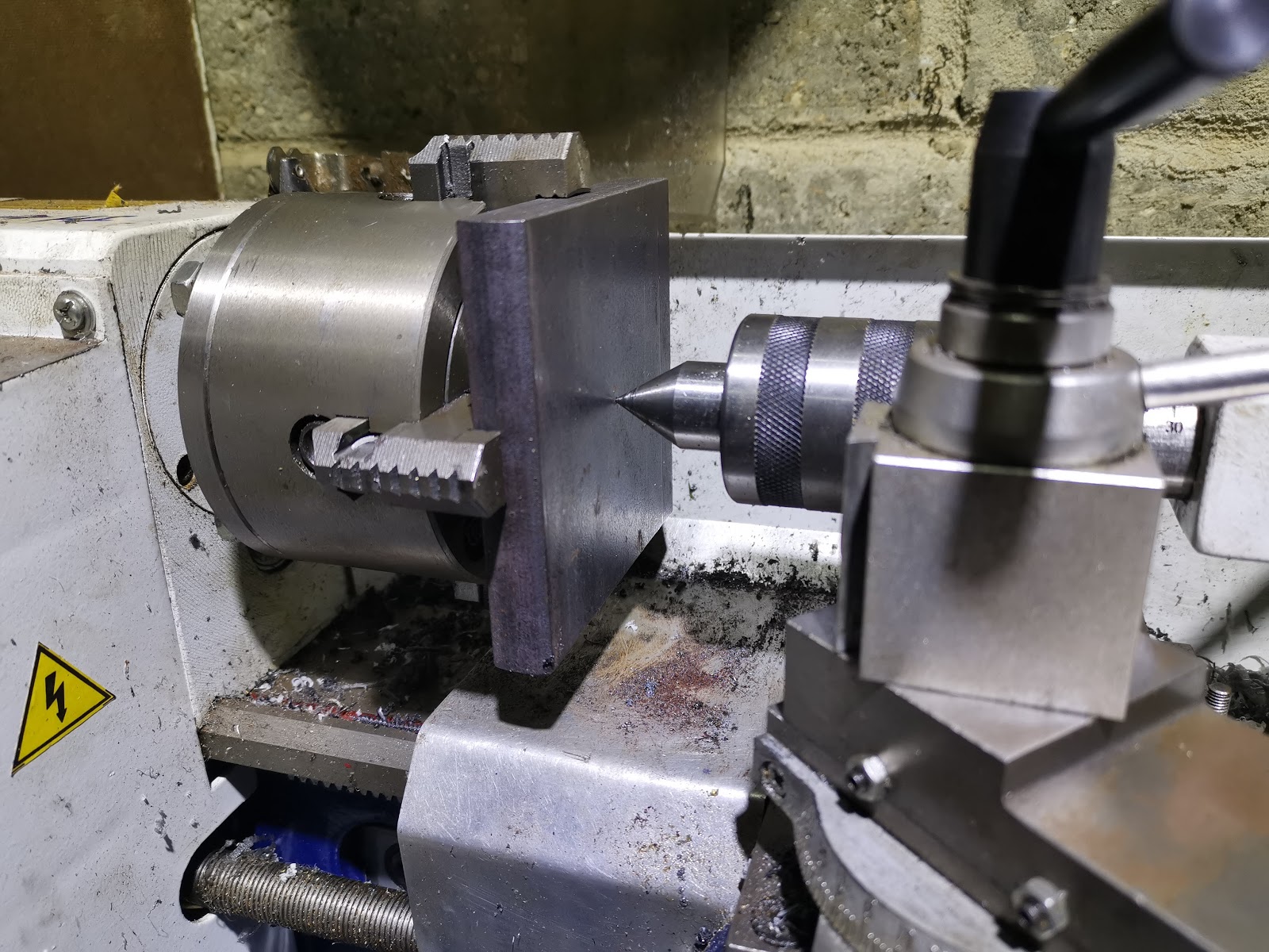
Here, the holes are drilled, the adapter is held in the three jaw chuck on the register which will eventually locate that very same chuck. I am machining the outside diameter and have started machining the register for the rotary table:

Now that the OD is machined and the fixing holes for the adapter to table bolts are drilled, we need to set the table up on the lathe in order to drill the chuck bolt holes and countersink the remaining table fixing holes.
I've bolted the vertical slide to my milling adapter plate, but as soon as I attempt to move the rotary table to the lathe centre I run into a couple of problems:

The next problems appear. While I have a few tee nuts, they are all M6 which is too small for the vertical slide and secondly, this sort of load reveals a lot of movement in the carriage. We'll need to stop and adjust that before we go any further.
I stopped the job for a while to adjust the carriage, modify the splashback (to make it easier to adjust the carriage) and add some cross slide locking screws. Read about them here:
I bought some M8 tee nuts and mounted up the rotary table again. I finished machining the three screw holes retaining the chuck adapter to the table, and then reversed the chuck adapter to drill the chuck mounting holes:

There are six holes - four spaced at 90 degrees for the four jaw and three spaced at 120 degrees for the three jaw, one of which is common to both chucks. They are counterbored 13 mm for the chuck retaining screws. These are in an awkward position and have to be tightened when the adapter is fixed to the table, and there is very little room. The screws will have to be adapted to reduce the head diameter. In the next picture, if you look closely under the rotary table you will see I am using the carriage stop to ensure all the 13 mm counterbores are at the same depth:

I'm very pleased that the holes line up with the M8 holes in the four jaw chuck. you can see the six holes here, with the hole common to both chucks closest to the camera:

As I mentioned, the chuck retaining screws have to be adapted to reduce the head diameter. I've fitted the ER25 collet chuck and turned the heads down to 12 mm from 15.5 mm. As you can see, they fit in the three-jaw bolts holes just as well as they fit in the four jaw:

Here's how you have to assemble the chuck adapter. As I said, the PCDs are such that the chuck screws are partially obscured by the rotary table, and of course you have to fit the adapter to the rotary table first. So, you assemble the screws to the adapter and then fit the adapter to the table and fix it down, then fit the chuck, gradually tightening down the chuck screws. It's a bit fiddly because you have to rotate the table as you go but it doesn't take too long.

Here we go, all together. I need a couple more modifications: the hexagonal locking screw for the rotary table needs either a 10 mm spanner permanently on the lathe, or maybe I will just replace it with an M5 cap screw.
Secondly, the locking screw that allows the table to be angled needs a longer tommy bar, or a 15 mm wrench permanently on the lathe. I think I will drill it through and add a permanent, sliding tommy bar.

Thirdly, the tilt function allows the table to drop when you apply a side-load, from a milling cutter for example. This has the potential to ruin your work - hence the toolmakers clamp in this shot:

But that's it for now.
Here's one - emulating the fuel and oil caps on the QR. I don't want to buy the bits - it would be too easy just to turn this into a cheque book rebuild, but I can use the tools and materials I have knocking about or cheaply available to make a functional and visually passable copy of the part I need.
You will have seen the oil cap post and maybe the fuel cap post - both of these are turned from Acetal but have features allowing the hand an easy grip. These features can be milled but to look good will need accurate positioning and that needs the work to be rotated in a controlled way such that the milling cutter can machine regular slots in the circumference of the part.

The way we will do that is to use a rotary table to hold and move the component a set fraction of a turn for each cut. Here it is - it's a 3" rotary table from RGD Tools.

I'm going to hold the work in a chuck - the three or four jaw, or maybe a smaller 3" chuck if I think I can use the space. In any event, we will need a plate to bolt the chuck to the table - an adapter plate. This is necessary because the rotary table has three T slots and the chucks have three or four M8 stud fixings.
I plan to make this adapter from this chunk of hot rolled (black) mild steel that I bought on eBay. In retrospect, this was a mistake - I probably spent more on replacement tool tips than I saved on the hot rolled steel. It has hard spots which are quite capable of wearing out HSS lathe tools or chipping carbide tools.
I didn't know that at the time.

Anyway, I marked the centre and faced it in the four jaw chuck.
I chopped the corners off in the disc cutter when I realised how difficult the material was to machine, which made it a bit easier to machine the register for the chuck. The rotary table has a 5 mm centre hole which I have drilled and reamed in the adapter:

The register is turned a few thou' undersize and fits the back of the chuck beautifully:

While it was still on the lathe, I marked the PCDs of the bolt holes:


Here, the holes are drilled, the adapter is held in the three jaw chuck on the register which will eventually locate that very same chuck. I am machining the outside diameter and have started machining the register for the rotary table:

I've bolted the vertical slide to my milling adapter plate, but as soon as I attempt to move the rotary table to the lathe centre I run into a couple of problems:
- first, the leadscrew on the vertical slide fouls the body casting. In this application, it has way more movement in the upward direction than I need but not enough in the downward direction. The leadscrew is easily shortened by 10 mm which fixes the problem and reveals another one:
- the vertical slide hits the bed chip guard fixing screws. That's no problem, we will remove the guard

The next problems appear. While I have a few tee nuts, they are all M6 which is too small for the vertical slide and secondly, this sort of load reveals a lot of movement in the carriage. We'll need to stop and adjust that before we go any further.
I stopped the job for a while to adjust the carriage, modify the splashback (to make it easier to adjust the carriage) and add some cross slide locking screws. Read about them here:
- http://ariel-square-four.blogspot.com/2020/03/mini-lathe-qd-splashback.html
- http://ariel-square-four.blogspot.com/2020/03/mini-lathe-cross-slide-lock.html
I bought some M8 tee nuts and mounted up the rotary table again. I finished machining the three screw holes retaining the chuck adapter to the table, and then reversed the chuck adapter to drill the chuck mounting holes:

There are six holes - four spaced at 90 degrees for the four jaw and three spaced at 120 degrees for the three jaw, one of which is common to both chucks. They are counterbored 13 mm for the chuck retaining screws. These are in an awkward position and have to be tightened when the adapter is fixed to the table, and there is very little room. The screws will have to be adapted to reduce the head diameter. In the next picture, if you look closely under the rotary table you will see I am using the carriage stop to ensure all the 13 mm counterbores are at the same depth:

I'm very pleased that the holes line up with the M8 holes in the four jaw chuck. you can see the six holes here, with the hole common to both chucks closest to the camera:

As I mentioned, the chuck retaining screws have to be adapted to reduce the head diameter. I've fitted the ER25 collet chuck and turned the heads down to 12 mm from 15.5 mm. As you can see, they fit in the three-jaw bolts holes just as well as they fit in the four jaw:

Here's how you have to assemble the chuck adapter. As I said, the PCDs are such that the chuck screws are partially obscured by the rotary table, and of course you have to fit the adapter to the rotary table first. So, you assemble the screws to the adapter and then fit the adapter to the table and fix it down, then fit the chuck, gradually tightening down the chuck screws. It's a bit fiddly because you have to rotate the table as you go but it doesn't take too long.

Here we go, all together. I need a couple more modifications: the hexagonal locking screw for the rotary table needs either a 10 mm spanner permanently on the lathe, or maybe I will just replace it with an M5 cap screw.
Secondly, the locking screw that allows the table to be angled needs a longer tommy bar, or a 15 mm wrench permanently on the lathe. I think I will drill it through and add a permanent, sliding tommy bar.

Thirdly, the tilt function allows the table to drop when you apply a side-load, from a milling cutter for example. This has the potential to ruin your work - hence the toolmakers clamp in this shot:

But that's it for now.
No comments:
Post a Comment