Saturday, 7 April 2012

Building up

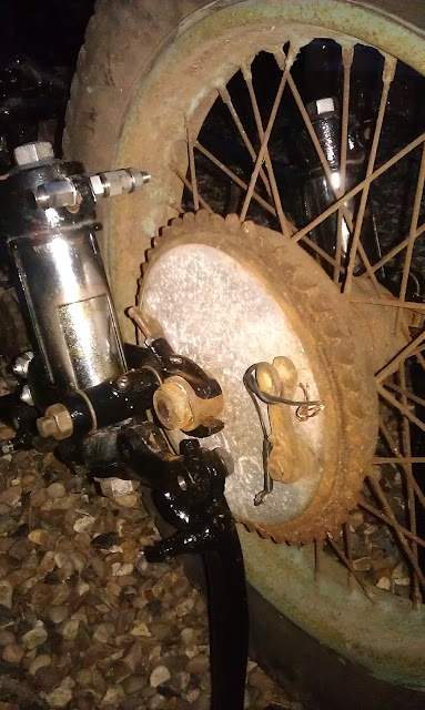
So, a few shots of half an hour's work, putting in the yokes:

Bottom bearing greased...


Steering damper parts all assembled. All from Drags bar the star washer and centre stem which are original


Top bearing greased


Bottom yoke in & bearings adjusted.


On to more serious work...

So, a while ago I promised to share the contents of some cool eBay finds...

These were a set of mudguards and chainguards I found in Doncaster, which were won at a very reasonable price and duly arrived. They were wellmarked and  photographed by the seller, and I knew I was in for some serious welding.

Here is the worst of the rear guard:


Here's one of the upper L-stay lugs, broken off and thoughtfully retained by the vendor:


So essentially we have a maze of cracks in each of the lugs for the L-stay at the top of the mudguard, along with two large holes left by a pillion seat fitted in the dim & distant past.

The metal is also very thin in these areas, badly pitted by moisture retained by a seat bracket that was still fitted when I got the parts.

There are also cracks at each of the lifting handle lugs. and a worn hole where (I guess) the chain guard rubs against the mud guard.
Unknown at the time of taking these pictures was the long crack above the chainguard recess.

A while ago I realised that the number plate that I had was a later BSA pattern, repaired it with the trusty MIG welder and sold it on eBay, to further fund the Ariel rebuild.

Of course, the holes for this are not the same as the ones I need and will have to be filled, along with the pillion seat holes and any others that I find I don't need - but then, this is the main purpose of the non-cosmetic Phase 1 build.

I've mentioned the fantastic AOMCC forum once or twice. Yet again Brenton Roy comes to the rescue with some photos of his Dad's '51 SQ4:

Here are the pillion mounts on Roy's bike's rear mudguard, looking down to the front mudguard mounts:
Front mudguard mounts in more detail. My mudguard has the front stay inside the mudguard bade.
Here is the routing for the rear light cable - presumably that is the end of the ignition coil. I'm not sure where mine fits yet.
And here is the whole rear end. I'm not fitting a pillion seat, though I am going to repair the holes left by the previous one, and reinforce the mudguard at those points in case I change my mind. That way I will have powder-coated a mudguard that is strong enough to be re-drilled for a seat.

This is what it is supposed to look like. You can see the L shaped stay and the lifting handle:


Friday, 30 March 2012

Charlie's Shed - Corks

This week, I have been mostly cutting up pieces of cork...


So while waiting for my fork tools to arrive, I have been cleaning up the petrol taps.

After several sessions in a hot ultrasonic bath, we have two clean Enots petrol taps, the type with the famous 'HexagON'. One is a reserve tap in that it has an additional reserve lever - so the bike will have three options - one side of the tank through one tap, the other side of the tank through the other tap, and a portion of fuel available from one side of the tank with the tap in the reserve position. How useful.

So, after ultrasound we have the Dremel & brass wire brush to buff up the nickel - which is has a distinct 'patina' brought on through years of service and inappropriate spanners. Nothing to stop them working though, at least, nothing that a new set of seals won't cure.

So, rummage around under the bench for the remains of a 1/4" thick cork table mat, and we can set about making some new ones:
  • make a wad punch out of some 15 mm tube, sharpened at one end
  • whack the punch into the cork with a mallet, onto a stout hardwood anvil
  • realise this only crushes the cork
  • think again and resharpen the punch
  • screw it into the cork to actually cut the seal blank out
  • do it five more times
  • stick a dowel inside the tube and push out your six blank seals
having crawled around the workshop floor, since they shot out of the punch and went everywhere, go and have a cup of tea. Next:
  • punch a small (4mm or so) hole in the centre of each blank
  • thread each seal onto a suitable screw, retain with a nut & washer
  • chuck the screw in an electric drill, or a lathe if you are lucky
  • using a 60 grit sanding pad, followed by 120 grit, reduce the seals to 1/2" diameter in your makeshift lathe
  • strip it all down and admire your handywork.


Next, oil the seals and wait a little while. Now you can put them in the taps, reassemble and revel in the fact that you have saved yourself £3.50!

Thursday, 15 March 2012

So, where are we?

This is going to be the most boring blog post ever. It's sole purpose is to try to force my thoughts to coalesce into a course of action.

To summarise where we are - the rear suspension (apart from the stand mounts and the spring) is done and the back wheel is on. The gearbox could be bolted if I were to determine which studs I had and which were missing.

The fork legs are together, but I don't have the tools to screw the seal housings in place and one of the seal housings is dented - no matter though, I will fix that when I do the Phase 2 cosmetic rebuild. One of the top shrouds has a large hole in it - again, one for Phase 2. The yokes are together, but I am missing the fixed plate for the steering damper and the handlebars - both on back order from Drags.

So, if I had the puller for the fork legs, and the handlebars I could put the forks together in the frame; if I had the bolt for the brake plate (the torque reaction bolt) I could put the front wheel on; if I had all the bolts for the mudguards I could fit them, and then I could start mudguard welding.

So I need:

  • front brake torque bolt
  • front & rear mudguard bolts
  • an assortment of nuts & washers
  • fork leg puller & oil seal holder tool
  • the bolt for the steering damper fixed plate
I need a trip to Drags... roll out the Bantam!

Thursday, 8 March 2012

A leap ahead

Well, the sun is out, the old MZ TS125 is going for it's MOT and the tools are all out in the garden. At the end of the work day I'm needing some distraction and there are some Ariel stand parts lying around in the office... why not fit up?

The new stand with it's stainless fasteners goes on easily, so let's try the rear wheel in place:


The stand spring stud doesn't fit though, unless I have misunderstood. There is no undercut on the stud and a full depth tapped hole in the frame (more work for the 3/8" CEI taps), so it won't screw fully home. Looks good from the offside as well though. We also now know that the G1/99 double ended tube spanner in the toolkit needs to be 5/8" BSW, at least at one end...


And with the gearbox in place maybe we are OK with the chain alignment. It looks fine from this rudimentary view, but the problem is supposed to be with the clutch and the primary chain, so maybe we are not out of the woods yet!


Then we can lay the un-repaired mudguard over the top. It is now obvious where the stays, the lifting handle and the frame bolts fit. It is also obvious that the bracket on the top is for a dual seat that we won't need. another missing part springs to light though, it looks like two of the QD hub nuts are missing. The chalk 'X's', by the way, are cracks that have yet to be repaired!

Tuesday, 6 March 2012

Forks

So, the skirmish aimed at getting the rear wheel in place, in order to confirm that the gearbox mainshaft is the right length, has morphed into a campaign to make a rolling chassis. This means I will have to clear out and rearrange the summer house and face up to the awful prospect that the Ariel may be too big to fit into the only covered space available to it.

Bouyed up by some successful welding over the weekend (fitting Ford Ka seats into the Morris) I’m now almost ready to tackle the mudguards – hence the need for a rolling chassis. I’ve also bought the parts for the rear stand, necessary to get the wheel & gearbox in, and I bulked that order out with the fork parts & the handlebars – all from the ever-reliable folks at Draganfly.

As the forks came out of the boxes, we had the top yoke & the sliders in new gloss black paint, the stanchions & bushes rusty in rolled up newspaper, and the bottom yoke & shrouds somewhere in between – gloss black paint but plenty of rust as well. As well as a large hole worn in one of the stanchions. Another job for my newly acquired welding skills.


Some of the smaller pieces, like the top nuts, the races, and the adjusting nuts for the races were in the toffee tin full of fasteners.

So we’ve got all the bits out and surveyed the damaged and the missing. Missing is mainly confined to fasteners and the steering damper plates and friction discs – the special nuts at the top and bottom are gone too. The shrouds with the headlamp ears are nicely wrapped in newspaper, in the boxes - we've been quite lucky here. 

The ‘damaged’ list is far longer – virtually all the threads are mangled to some extent, either burrs, paint, chunks missing or dents – but nothing that can’t be fixed. The brass bit on the steering damper stem won't take it's nut, so something is wrong there.

Stripping it all down, a few hours with emery cloth and wet & dry paper reveals stanchions that are in good shape, under the rust. I haven’t checked them for straightness yet, but the sliders seem to move smoothly and without much play. The lovely gloss black prevents the chrome oil seal holders, and the front wheel spindle from fitting though. the adapters at the top have seen the attention of a bad attitude with a hammer - two mangled threads that will go straight in the bin. Five minutes with the blow lamp & Stilsons sorted them out.


With parts from Drags, we can assemble the steering damper and the yokes – the 3/8” CEI taps have seen some action this weekend!

Top adapters are back in, bolts & washer cleaned up (rechrome in Phase 2), new clamp bolts, new seals, no new bearings though.

I am going to refresh the races with new balls for the moment, and in Phase 2 I will change them for taper rollers. I don't want to do that now in case I trash them preparing for powder coating the frame.

So, next jobs – we have some of the steering damper parts – some are on back order. We need to clean the paint out of the slider threads and spindle holes, and we need to repair the hole in the top shroud. Then we can put each leg together, and look at the springs, and pull them into the bottom yoke. I need to finish trial fitting the top yoke.
I’ll also need to make or buy the tools for pulling it all together!

Monday, 27 February 2012

Frank's Linked!

So, time to start assembling. This shows the rebound springs, the sliders, their posts & pins in position on both sides with the chrome shrouds slid into the frame. Above these are the main springs with their caps, ready to be pulled in.

Missing from this first picture are the stand brackets which have to fit on the end of the springs, the horseshoes and the links.

In the background, you can see the rear wheel waiting in the wings!
The next step is to pull the springs into place and fit the nuts and the stand brackets to the bottoms of their pins. This is not too difficult, since you can trap the slider against the bottom of the frame with a G-Cramp or a cargo strap, and compress the rebound spring; then you can get another strap or clamp on the top of the pin, against the bottom of the frame again, and pull the main spring down until the end of the pin emerges through the hole in the bottom of the frame lug.

When you've done all that, you can slide the stand bracket into place over it's lug and put the bottom nut on - the only difficulty I had here was to get the pin central enough to get the nut on.
Pushing the slider around allows that to happen OK.

The next step is to add the horseshoe, it's pin, knurled washers and nut. That done, you can put the links on and wiggle the pivots into place.

All I need now are some stainless washers & nuts for the links; and some suitable stainless fasteners for the stand brackets.
I've put an order in to Draganfly for the rear stand, the springs and the mudguard stay mounting studs. While we wait for the parts to arrive, we will have a look at the forks.

Watchmaker...

So with the odometer and the speedo drive sorted out, it was onto the movement and the case. This is the movement as it emerged from the case:

The movement appeared intact on inspection, indeed it was just caked in grease and the debris from the mangled drive wheel. It was a simple matter to strip it down, then we sorted the various assemblies into separate pots for cleaning with pegwood, solvents & the ubiquitous toothbrush. Look at the colour of the solvent:


This took several rinses, followed by polishing of the wheels & arbors.  There wasn't any tooth damage to the wheels, and the various pivot holes in the plates are all in good condition.


Reassembled & lubricated the speedo now works nicely in the electric drill.The picture below shows it in position in the main frame, hooked up to the main drive & the odometer. We cleaned the odometer wheels (very gently) with a swab dipped in a mild water/detergent solution:


Next stop was the case, which required a trip to the shed to find the top yoke, since there was no strap for the speedo and no idea of what it should look like. A cardboard template and some of the inevitable sheet metal work soon remedied that problem, and the case was rubbed down and sprayed gloss black. The picture below shows the speedo in position in the top yoke, from underneath:


The dial and needle we left mostly as found - we don't want to polish all the patina away. I had the lamp holder still attached to the original wiring harness, so this was polished up using brass brushes in the Dremel, wired up and fitted back in place. some new M6 nuts finished the job - since the design of these instruments originated in France, all the fasteners are metric.

Tuesday, 14 February 2012

I love eBay...

After months of searching, I've found the correct S467/3/L speedometer for spares or repair on eBay! It looks good in the picture!

When it arrives, it's well wrapped in a box, inside 3 jiffy bags with newspaper around the outside. So, as soon as possible, we spin it up on the drill and...nothing happens. Well, the trip works and the odometer would probably have worked if I had bothered to wait...

If you've read the Bantam article, you'll know that I've repaired these before. When I got this one apart, we found the drive pinion spread around the interior like fairy dust. It shown in the pictures, minus all it's teeth.

As luck would have it, I had a Bantam 'D' speedo in the spares box, with it's drive spindle intact. This fitted straight in.

So next, I dismantled the trip/odometer drive (as you have to do, to get the drive spindle in or out) and cleaned up all the dust with a stick of jewellers pegwood, with a cloth swab taped to it. A dose of lighter fuel on the swab cleaned it up beautifully. Reassembled & lubed up it works perfectly.

Next job, number wheels. A similar swab but this time with a weak detergent mix cleans all the oil & grease off those as well.

Then we get on to the morass of goo that covers the movement. More later.

Sheet Metal Shop

Way back when, every engineering student spent time in the workshop with a scriber and square, an engineers hammer and a dot punch, and got his fingers covered in marking blue. The lecturer would be at the front of the shop in his white shop coat, explaining how you had to wash your hands before you went to the loo, because you were a real engineer now and you didn't want any nasty skin infections.


Then you'd spend the day marking out, witnessing, sawing and filing a tack lifter that would spend the next 30 years at the bottom of your toolbox. The enthusiasts would eat that in a couple of hours and move on to a 5" gauge Flying Scotsman or a 1/12th scale Avro Lancaster - such were the days before 'Call of Duty 4'.

Actually, my bias went more towards making myself some mudguard stays for my Matchless or welding up the holes in my Austin Healey Sprite.

However, you don't forget those manual skills, and somehow they are much more valuable than the office skills you learn later in life as your career takes off.

Here's the missing suspension washer and a new clutch screwdriver, copied from the W/NG manual.

Tools

So, more work this week on several fronts. It may interest the polyamide quilting moguls of the world that I have started to collect Ariel tools.

No... I've been through the parts lists for the SQ4, and checked all the tools the toolbox is supposed to hold. I have looked at Drags website to see which ones I can buy. I have obsessively trawled eBay for examples of tools marked 'Ariel'. I have printed the W/NG spares lists, and the handbooks, because these have pictures of all the tools.

And I have retired to the deep, dank, dark & smelly recesses of our cellar workshop to make the ones I cannot find...

Monday, 6 February 2012

Amelia's Plungers

So, we spent the weekend cleaning, painting & collecting pieces of suspension from the boxes the machine was delivered in. We are missing a washer (!) which will have to be made and we were missing the two large upper shrouds (the ones with the slots in) which came from eBay, with better lower shrouds than the ones I had.

Generally the bushes are good - the tubes along which the sliding members move are a bit pitted in places. Some threads need recutting as well.

The chrome plating done by the previous restorer is flaking and will have to be removed - the link pins are especially bad. However since the first build is to be non-cosmetic, we will leave these for now.

Draganfly have the rear stands in stock, so when I have acquired the material to replace that washer we will take a trip down there and pick one up, along with the springs, the mudguard stay fixings and various other small parts. We'll go to Mike Peters at www.polished-stainless.com for all the stainless fasteners (as we did for the Bantam).

However for now, the plungers are loosely fitted in the frame:

And this is what it will look like:


Frank's Links

So, to bike building, starting at the back.

My Square Four, like many others is fitted with the famous Anstey Link rear suspension, designed by Frank Anstey to overcome the chain-tension problems inherent in the plunger design, whilst avoiding the complex frame re-engineering required when providing a true swinging fork. Mr. Anstey joined Ariel from Triumph, as Ariel's Chief Designer, in 1937. Here's an extract from Patent 498544, filed by Ariel Motors & Mr. F Anstey on 16th December 1937:

Patent Number 498,554. Spring frames for motorcycles. ARIEL MOTORS, Ltd., and ANSTEY, F. Dec. 16, 1937, No. 34840. [Class 136 (iii)] A spring mounting for the rear wheel of a motor-cycle comprises in combination, ...on each side of the wheel, a lever j arranged horizontally or nearly so at the rear end of the frame a, one end of the lever receiving one end of the wheel spindle m, as by means of a slot k, a fulcrum piece g having a pivotal connection, i with an intermediate part of the lever j means for carrying the fulcrum piece g on the frame so as to allow it to move in a vertical or approximately vertical direction, and means for attaching the other end of the lever j to the frame so as to allow this end to move in an approximately horizontal direction, as by means of a vertical link n or a horizontal guide, the movements of the parts being controlled by one or more springs.; The fulcrum piece g is slidably mounted on a guide pin f secured in a bracket c formed on or attached to the rear end of the frame a, the sliding movement being controlled by a main spring h and a rebound spring or rubber buffer, with or without a vibration damper, such as an hydraulic damper combined with the guide pin mounting. The lever j is formed with a forked part passing around the bracket c, the pivot pin i extending across the forked part. Thesprings are enclosed in telescopic tubes t, u. The two levers j on opposite sides of the wheel may be interconnected by links &c. and controlled by a single spring or set of springs

The  design uses all the 'normal' elements of a plunger suspension, but instead of suspending the wheel from sliding member it incorporates a cast steel horseshoe, which carries the wheel and pivots on the sliding member. This horseshoe is retained by a link, pivoting above the lower frame members and forward of the plunger allowing the horseshoe to travel through a short arc so that the drive chain tension was kept more constant during compression and rebound. Of course, this is not a perfect solution since the centre of the horseshoe's rotation is still a long way from the gearbox sprocket centre, but it is a lot better than a conventional plunger.

Of course, there are lots of pivots, sliding members & bushes to wear out...

Here are the bits I have acquired:


You can identify most of these from the sketch above. The long screw poking out of the horseshoe (and painted that WD green colour) is the chain adjuster, which replaced the snail cams. You will also see that my '51 bike has volute-type rebound springs in place of the previous coils.

Wednesday, 1 February 2012

Gearbox. Woes?

So, in a change from electrics, we have had an anorak moment with the gearbox. Reading part numbers (ZZZZZzzzzzz.....) and looking through the parts books, we find that the Squariel is supposed to be fitted with a Burman BA gearbox, with a part number staring with G106.

All not very interesting, until we see that our gearbox number is G107J51, which means it is a G107 gearbox built in November 1951, several months after Amelia was sold in sunny Leytonstone.

The problem is... the G107 is from a different Ariel with a different mainshaft and probably doesn't fit! what are the chances of finding the correct box? why did I buy a bike in bits?

But but but.... I feel a plan coming on. How will I figure out if it is OK? the folks on the AOMCC forum says it is all about chain alignment...

So, the plan is that we assemble the bike enough to check the chain alignment. I'm not sure if it will be the primary or the secondary chain, so I'm going to build up from the rear wheel to the primary cases and see where it goes...


To see how this story turns out, go to this post...

and to see how I rebuilt the gearbox, you can turn to this one.

Tuesday, 17 January 2012

A few more electrical items


Well, not much to add this weekend. We've been very busy with work, paintwork for an MZ TS125 and a poorly VW Beetle with inlet manifold leakages. 
All we've managed to do is strip and repaint the dynamo end cap and the regulator. We used Hammerite Kurust on some parts of the regulator, at double strength, which seems to work very well. The parts are painted with high street acrylic aerosols & U-Pol etch primer. The end cap is from the original Lucas CF35D dynamo, the rest of which is still attached to the engine. The regulator is a 1962 Lucas MCR2, with a brass case which though a later replacement part is correct for the machine


Friday, 13 January 2012

Ammeter Finished

So, here is the finished article. The ammeter has been stripped & cleaned inside & out and is now working happily.

The chrome on the rim is good, and the case has been repaired.
This is the new ignition light. The design & material selection is inspired from the genuine ones I have seen on eBay and the various forums, particularly the C10/C11/C12 forum. It's not an exact replica of anything but it looks the part.

I've made a carrier from 2 mm Tufnol which is a little thick, but all I had. The lamp bracket is made from 0.5 mm brass sheet, with insulation gaskets as necessary, riveted together. The one thing I would like to find now are a couple of 2 BA thumb nuts to replace those steel hex nuts.

Monday, 9 January 2012

Almost a red spot ammeter

Well, here is the first of the post-Christmas presents!

This is the kit of parts that I have, now that I have stripped a Lucas red spot ammeter that I bought on eBay from a member of the AOMCC, for a lot less than one can spend on such things.

It is a bit of an oddity. It seems genuine, it has a Lucas part number and is made of parts of approriate 'quality'. It is marked '1980', and I guess it was a replacement part for vehicles still using red spot ammeters. It is marked 'Lucas' on the dial, but it does not have a window in the back, like the earlier versions that would have graced Amelia's curves when she was new, and it has no facilities for an ignition lamp internally so it could not have functioned as the red spot ammeters were intended to do.

The plan is to replicate the parts used for the ignition lamp and to cut the window through the ammeter, so that we end up with a suitable white faced ammeter with the functionality that we need.

So, starting the work. Here is the back plane of the meter, with it's insulator. I've marked out the holes I need, and I've drilled a pilot hole in each. Then I have taken my piercing saw with it's V-table and carefully cut the shape we need for the ignition lamp aperture. I've cleaned the hole up with needle files.
Here is the back of the ammeter, the back plane and the insulator, all assembled and showing the aperture lined up. Not quite right yet.

Here's are the prototype parts for the ignition lamp. Following the style of the original ammeters, I have used a plastic card to replicate the tufnol insulator that is used to mount the lamp holder, just to get the shape, and the position of the lamp correct in relation to the aperture on the back of the meter.

The lamp holder is mounted on a small piece of 0.5 mm aluminium sheet, pop riveted to the insulator. There is a plastic insulator between the centre terminal of the bulb holder and the mounting bracket.

So for now, the lamp is in the correct place. We will reassemble and see if it looks OK from the front, when it is illuminated, then we will make some nicer parts.

Here it is, put back together with the ignition lamp off...

And here it is with the ignition lamp on! Isn't it exciting!

Monday, 2 January 2012

Headlamp almost there

So here are a few pictures of Christmas holiday activities. The chewed pilot light housing has been filled & built up around the front edge as a low-risk alternative to a welded repair - I figured I would rather try this approach and have to redo it than melt an original SSU700 headlamp housing with clumsy welding.

After going through the grits with the help of some knifing stopper the headlamp shell is now looking very smart.

I have ordered some W-clips; I have rubbed down the newly straightened rim and I will order a plating kit after the holidays.

Then I plan to plate all the screws and maybe the rim as well.

And hopefully there should be a Red Spot Ammeter in the post!