Thursday, 24 July 2014

Mighty Morgo

Today I fitted the Morgo oil pump made by Autovalues Engineering from Bradford.

The Morgo is a gear type pump, and is very nicely manufactured, well packed and is provided with a comprehensive set of instructions. While there are several Morgo rotary pumps for other Ariels & Triumphs, the fitting kits and instructions are bespoke to the model you are fitting. Very nice quality, well thought out.

The pump comes with a fitting kit, consisting of the left hand drive nut, a set of shims, a gasket, two tab washers and two mounting bolts


This is the drive side of the pump, showing the Oldham coupling used to drive the pump from the camshaft.


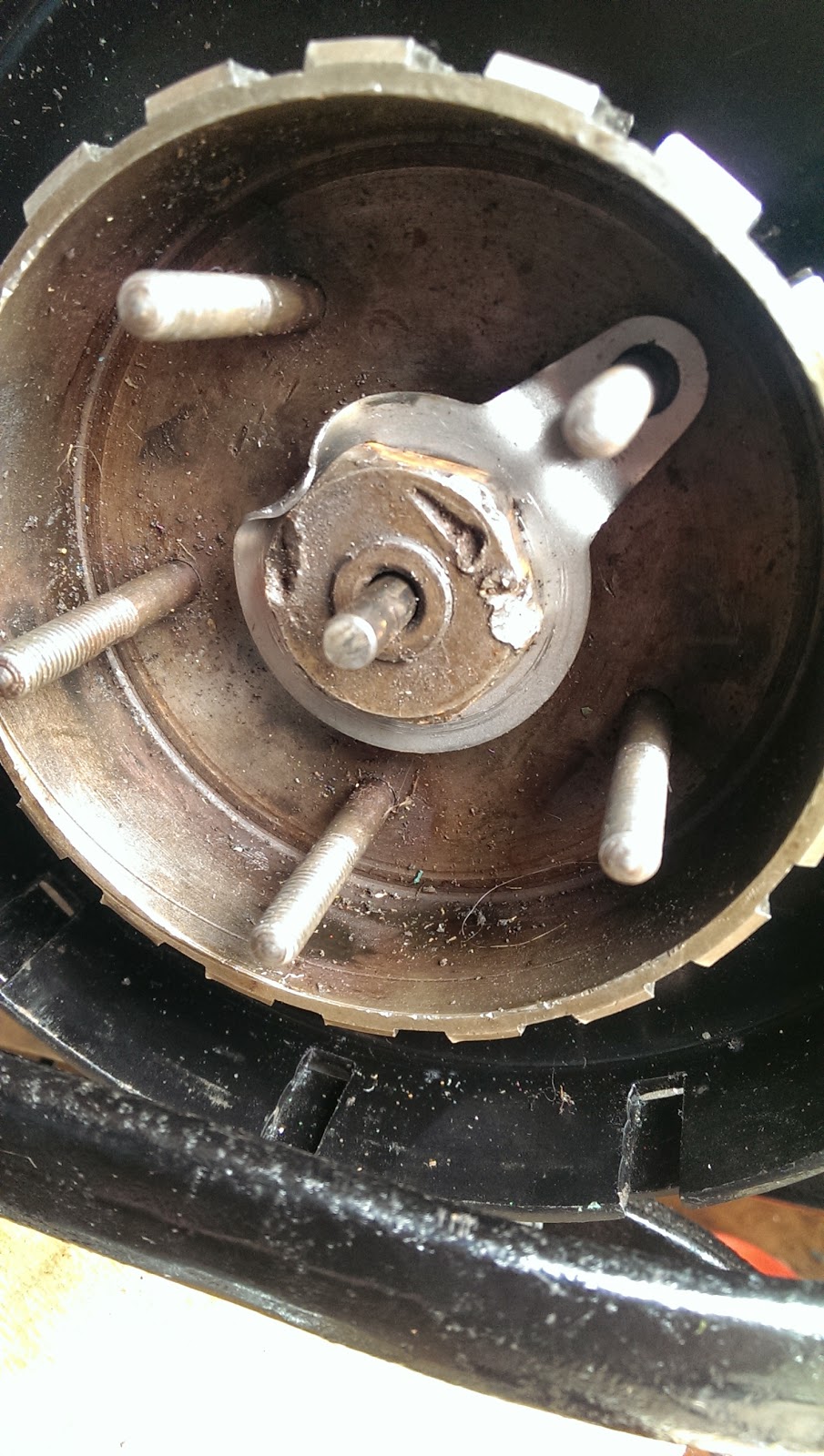
And here is the drive nut for the pump. Those slots are closely toleranced to prevent rattles and wear


Here it is in place. I've got it fitted with the original studs at the moment, since I don't like the idea of wearing threads in the soft crankcase to remove a service item but in practice you have to engage the pump coupling before bolting up - it is close fitting in its slots, as it needs to be, and this makes the bolts supplied with the pump the only practical way of fitting it.


I need to prime the pump - so I will refit it with the bolts supplied with the pump.


Tuesday, 22 July 2014

Throttle Cable

I've had the throttle cable set up like this for a while:


As a few folk on the AOMCC forum have pointed out, it doesn't work very well. First off the cable outer doesn't have a good abutment in the stainless steel bracket; secondly, the volute spring (granted it is the wrong one) has way too much internal friction to return the throttle successfully; thirdly, the cable run is poor, both due to the bracket and the volute spring.

But mainly, with the Solex carburettor and its butterfly throttle valve, the cable return spring is the only method of closing the throttle - so if it is not working well, you are going into the back of the braking car in front (and I have done that before) or that expensive rebuilt engine is going to disappear in a mass of tangled aluminium.

So, now I have this:


I have removed the volute spring entirely, and I have a stiff coil spring in its place. It's attached to the dynamo strap with a stiff wire link, and it has a little brass sheet link to attached it to the carburettor cable clevis pin. The throttle returns beautifully now.

I need to adjust the cable path by bending that bracket a little more, and I'll plate that spring later.

Sunday, 20 July 2014

Great strides...

Masses done this weekend.

I started by trimming up the HT leads and setting the distributor position, followed by the ignition timing - easy with the timing cover still off.

Next I stripped the primary drive & the clutch, pinning the engine shock absorber and bolting up the inner case.

I pulled the outer cover off the gearbox, and removed the gearbox mainshaft. I wanted to check that I had greased the sleeve gear, which I had - too many stories of those bushes seizing! I thoroughly greased the gearbox change mechanism and the kick start parts, before bolting everything up and fitting the clutch.


For some reason the new clutch centre nut does not fit - tight on the thread. I'll have to use this old one, for extra 'patina'...

Next, the clutch cover. This has never been fitted with the exhaust in place and, as predicted by several AOMCC forum members, the exhaust fouled the clutch cover.

This was easily remedied with a little metal work, and I produced a professional looking dish in the cover with a hardwood block and a deep socket.

I fitted the rear chain and chainguard too, using my usual ty-wrap method:


Next, the smaller oil lines. These are very soft copper and are easily bent by hand.


Thursday, 17 July 2014

Time to admit I made a mistake...

This, I have to admit, is a KH tank. It is a shame that I painted and lined it but it does look very nice!


This however is a Mk1 Square Four tank, which I bought from Jorgen Andersen of the AOMCC; it too will be very nice once it has had some treatment from a nice man with a welder and a can of Sureseal - oh, and a gritblaster, some lead, and some paint in various colours

 It has the bonus of being fitted with a better filler cap than my one


But it does have some dents, a mounting that is full of either weld or chemical metal, some holes around the edges, and some rather dicey looking threads. Its got the right tap (though it is in poor shape) and it has the crossover pipe.

It has some original red paint underneath, which happily looks very like the red I used on the wheels.


This is not so nice but it will add to the experience!

Monday, 14 July 2014

Next steps

The build so far has shed light on a few issues, so I'm going to make a list of what I have to do next:
  • finish the valve timing. I need to get the DTI on the engine again to ascertain where the cams are going me peak lift - I currently believe this is about 15 degrees early, so I need to measure that precisely and adjust it
  • when that is done, the Morgo oil pump can go on
  • I have no hose clips on the oil lines - I need to take the oil tank out to fit them, and I need to fit the rocker oil line
  • whilst the oil tank is out I will fill the gearbox. I also want to make sure the sleeve gear is properly greased, so I will remove the clutch and mainshaft to do that, and I can finish off the primary case (sealing) and shock absorber (split pin) followed by the chain and chain guard.
  • Then I will fit the oil tank and prime the oil system, and fit the sump plate
  • Connect up the HT cables (so i know which distributor connection is #1) and time the ignition
  • Sort out the carburettor throttle return spring and fit the throttle cable properly
  • flash the dynamo to change to negative earth
  • finish the earth cables in the headlamp
  • commission the electrical system
  • fit the fuel tank and fuel lines
  • turn the engine on the power drill
And then the moment of truth will be upon us...

Friday, 11 July 2014

It's been a while...

About a month actually. Ariel time in the last 4 weeks has been spent on a number of fronts: 
  • welding cable guides inside the rear mudguard 
  • finishing the wiring 
  • messing about with the valve timing 
the latter item has been the most frustrating. I have a good set of guidance notes from Draganfly, written by Bruce Longman which I have followed religiously.

I assembled the head using only cylinder number 1, as I thought I would make it easy on myself and avoid having to turn the cam against four sets of valve springs.

Initially I tried the Waller-style method of aligning timing marks.


Having done this I turned the engine over to see the exhaust valve opening half way down the power stroke. Bruce says that sometimes the factory timing marks don't give the correct timing, so I tried again... and again... and again... eventually getting the timing discs and dial test indicator out to do the job the long way, all the while getting more and more proficient at releasing tension on the cam chain, removing the nuts, drawing off the crankshaft pinion before I could remove the cam shaft pinion... Always the same result.


Eventually I started doing this more scientifically, drawing the valve event charts and calculating overlaps & durations. This is what it is supposed to look like:


Frustrated with Cylinder #1, and confused by the fact that #1 runs backwards, I changed to #3 and drew another diagram:


This revealed that #3 was about 180 degrees out; while #1 inlet valve was correct and #1 exhaust valve was about 180 degrees out too. Confused, I thought about looking at #2, which was doubly frustrating because one of the pushrods would not go in the tunnel.


I set and reset valve timings for about a week, and then one day, looking at the rockers, pushrods and convincing myself that #1 inlet must somehow be on the wrong cam, I started looking at the #2 inlet pushrod problem when I happened to glance down the #1 inlet pushrod tunnel - to see the pushrod going off at a weird angle.

I now know it is possible to get a SQ4 pushrod in it's neighbour's tappet. #1 inlet was in #2 inlet's tappet, so it was operating from #2 inlet's cam! Now that I realise what I am looking at, it's obvious.

Ho hum. we live and learn. At least I found it before I pulled the head off again!

Sunday, 15 June 2014

Monday, 9 June 2014

Updating the MCR2 Voltage Regulator

As I've probably mentioned before, I'm a stickler for originality, at least visually. If there is a period component that will do the job, then that is the one that gets fitted. However, I'm not afraid to modify components to make them more effective.

A case in point is the voltage regulator...


The voltage regulator I have with the machine - or the box of bits - is a 1962 Lucas MCR2 - obviously a replacement for the original regulator. While this is perfectly serviceable, it is not suitable for the sealed batteries I have fitted in the Draganfly battery box, so I am going to fit a modern V-Reg dynamo regulator which is designed to replace the mechanical regulator with modern reliable semiconductors, and can handle up to 100W at 6V and even more for the 12V version, provided the dynamo is capable of delivering this power. This device is proven and reliable and is available in Positive or Negative earth, also to run a 6V system. 

New features include: Current limit to the field winding, allows excellent performance when using a 6V dynamo on a 12V system while not straining the dynamo. Tougher electronics, with the introduction of higher energy spark suppression to reduce spikes generated by the dynamo. Improved "thermal foldback" which progressively reduces output power if the regulator gets too hot, indirectly limiting the dynamo from excessive current. Better servo loop stability, with new electronics which 'predict' when the output voltage is nearly correct and control the field current earlier.

The V-Reg 2a will run a 6V system or by cutting a simple wire link will run a 12V system.

Mine came from Paul Goff.

Taking these apart is quite straightforward. You'll need a soldering iron, a screwdriver and a spanner or two. Remove those two nuts and the screw visible in the picture, which may be sealed in with wax:


Then you can take your soldering iron, and a solder sucker, and de-solder the various joints topside. The E and A terminals need the wires de-soldering and removing; the F terminal is more easily disconnected at the frame (the top joint in the picture) and at the back (which you usefully can't see). The D terminal can be de-soldered at the copper cup around the screw from the previous picture:


You can now remove the back plate and the armatures, and you will be left with the mounting base and the four terminals. The F terminal is staying put for the moment, since I will have to cut it off (and after that there is no going back):


The V-Reg has a convenient pair of T-slots in the heat sink which are spaced so that the mounting bolts fit the hole spacing in the old base. The old 'D' terminal is also still in place:


Its then a simple matter of connecting the wires to the terminals:


We will tidy up that wiring when we have tested it!

Sunday, 8 June 2014

It's Show Time Again!

The day dawns bright & shiny for the annual Sheringham Classic Car & Bike Show, part of the Sheringham Carnival celebrations.

A few bikes this year and even less photos! Beattie, my Bantam in amongst some Ducatis:


A very nice Triumph

A BSA C12 - a local bike, but I don't know the chap that owns it:

A nice Matchless G2CSR:

Monday, 2 June 2014

A sunny day in June

My Square Four tank, and it does appear to be a Square Four tank (very large and of the appropriate width; large filler, pressure gauge hole) has as I said two taps (it also has a drain at front RH and no crossover pipe). What I neglected to mention (or even realize) was that the taps are forward of the tank mounts:


As you can see, on a Mk1 these are very close to the back of the rocker covers and will get frighteningly hot, I suspect. It looks a little odd; the closest reference I can find to this arrangement is a rather nice '51 KH shown in an article in RealClassic, which has two Ewarts taps in a similar location. The curious thing is, I have scoured all the KH and SQ4 parts books I can find and they all describe a single tap.

Hmm... Is this really a Square Four Tank?

So, one plan is to use a pair of Ewarts type plunger taps, 3/8" BSP into the tank with horizontal outlets. I will then make a copper/rubber tube assembly to tie the two taps together into the single inlet to the Solex. An alternative would be to blank the tap hole on the RH, and use a two-level plunger tap on the nearside - but I am not sure I have room for that.

I will need a supply of tube, nipples and gland nuts to make up this assembly - and I guess I will make a tee out of some brass barstock. I'm not sure where to buy these parts yet...

On a brighter note, she is a very handsome machine:


Max is nonplussed


Ariel do not seemed to have paid a lot of attention to the maintainability of their machines. Two maintenance items in this picture, neither of them easily accessed AND I have removed the kick start lever. More positively, the oil tank is now hooked up.


The valve timing is done, with a little help from my daughter - assembling the cam chain tensioner is not a one-man job:


And the exhaust pipes are looking good. The eagle eyed amongst you will notice the clutch dome is still off:


I have discovered however that when I straightened the RH footrest hanger, I straightened it too much and it now fouls the exhaust pipe.

More wiring done this weekend too. Horn and Lucas 529 rear light fitted:


and I am not sure what to do about the throttle cable abutment:


Sunday, 1 June 2014

Number Plate

This page is a repository for number plate pictures...

Might be useful!


The rear mudguard is 53 3/4" from end to end.

These are from Brenton Roy's 1951 SQ4:


My 1951 SQ4: